Magnetic disk drive and recording method

a magnetic disk and recording method technology, applied in the direction of magnetic recording, magnetic recording, filamentary/web carrier operation control, etc., can solve the problems of insufficient magnetization of the magnetic layer, inability to read recorded data, and inability to achieve sufficient output, etc., to achieve the effect of improving the reliability of recorded data

Inactive Publication Date: 2008-04-22
HITACHI GLOBAL STORAGE TECH NETHERLANDS BV
View PDF14 Cites 26 Cited by
  • Summary
  • Abstract
  • Description
  • Claims
  • Application Information

AI Technical Summary

Benefits of technology

[0014]In this situation described above, it is probable that, while the write head passes over a data sector of 512 bytes, the head / slider contacts a projection and vibrations causing fluctuation of a flying height or generation of the off-track state occurs 2 or 3 times in the head / slider. Even if it is tried to detect fluctuations of a flying height at the timing for reading servo data when the head / slider vibrates with a high frequency, the vibrations may have often ceased at the timing. It is therefore impossible to interrupt the write operation by detecting the abnormal recording state. Thus, in order to improve the reliability of recorded data, a technique is required to interrupt a write operation by detecting vibrations generated in the head / slider while the head / slider is flying above a data area for writing data and to restart the operation for writing data after the vibrations cease.
[0015]A feature of the present invention is to provide a recording method ensuring improved reliability of recorded data in a magnetic disk drive employing the servo area data system. Another feature of the present invention is to provide a recording method enabling interruption of a write operation by detecting vibrations of a head / slider with high frequencies at which the head / slider vibrates several times for one data sector during the write operation and restart of the write operation after the vibrations cease. Still another feature of the present invention is to provide a magnetic disk drive enabling realization of the recording method as described above.
[0016]With the present invention, when a head / slider comes into contact with a projection present on a magnetic disk or any dust or solidified lubricant deposited during the production process and remaining thereon or generated after start of the write operation and the head / slider vibrates to disable the normal operation for writing data, an operation for writing data is interrupted once by detecting such an abnormal state, and then the write operation is restarted after the flying state of the head / slider returns to the normal one. Thus the reliability of written data is improved.
[0020]The present invention can provide a recording method enabling improvement of the reliability of recorded data in a magnetic disk drive employing the servo area data system. The present invention can further provide a recording method in which a write operation is interrupted, when vibrations of a head / slider with a high frequency at which the head / slider vibrates several times for one data sector are detected during the write operation, and then the interrupted data is written after the vibrations cease. The present invention can further provide a magnetic disk drive capable of realizing such a recording method.

Problems solved by technology

When the flying height is too high, a magnetic flux from the write head does not sufficiently reach the magnetic layer, so that particles in the magnetic layer are not sufficiently magnetized and are not aligned in the desired direction.
Therefore sometimes a sufficient output cannot be obtained during read operation of the recorded data, or the recorded data are degraded during passage of time even within a guaranteed period, which may sometimes disenable reading of the recorded data.

Method used


Image

  • Magnetic disk drive and recording method
  • Magnetic disk drive and recording method
  • Magnetic disk drive and recording method

Examples


Embodiment Construction

[0036]Outline of the Magnetic Disk Drive

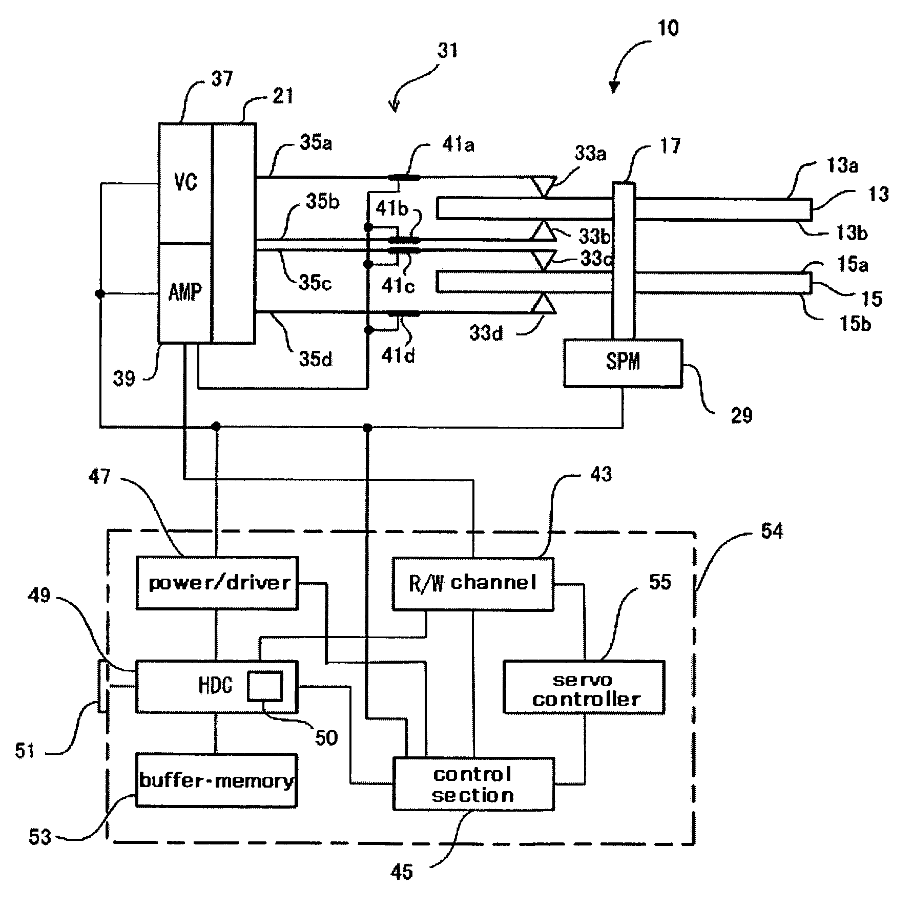
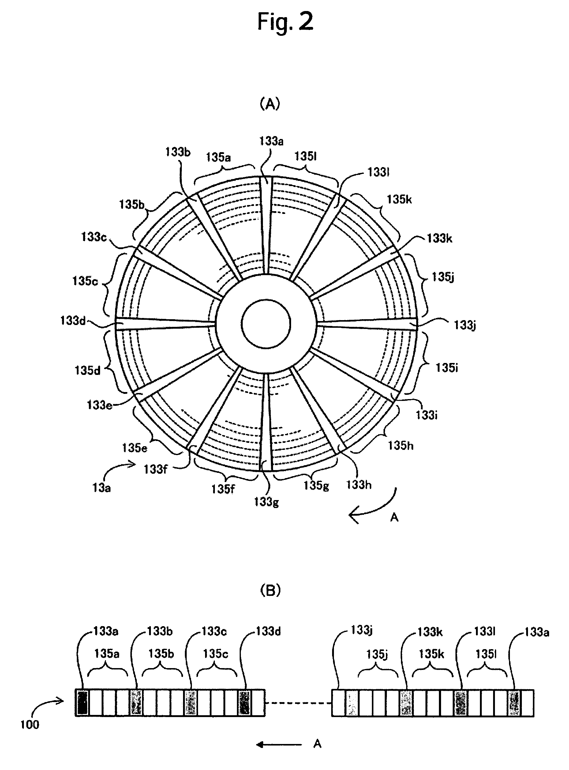
[0037]FIG. 1 is a block diagram showing a magnetic disk drive 10 according to an embodiment of the present invention, FIG. 2 includes diagrams showing a format of a magnetic disk 13a, and FIG. 3 is a general block diagram showing a head amplifier 39. In FIG. 1, magnetic disks 13, 15 are fixed with clamps to a rotor section of a spindle motor 29 provided on a base, and rotate together at a prespecified rotational speed around a spindle 17.

[0038]Each of the magnetic disk drives 13, 15 has corresponding two recording surfaces 13a, 13b; 15a, 15b. The magnetic disk drive 10 employs the data area servo system (also called the embedded servo system) as shown in FIG. 2. On each of the recording surfaces 13a, 13b, 15a, 15b, there are provided a plurality of servo sectors 133a to 133l each radially arrayed with an equal interval therebetween as shown in FIG. 2(A) illustrating a case of the recording surface 13a, and servo data is written in each of the ...


PUM

PropertyMeasurementUnit
timeaaaaaaaaaa
rotationaaaaaaaaaa
magnetic fluxaaaaaaaaaa

Abstract

Embodiments of the invention provide a recording method capable of improving reliability of write data in a magnetic disk drive employing the servo area data system. In a magnetic disk drive according to one embodiment, vibration of a head / slider can be detected with a vibration sensor attached to a head support mechanism. Writing of user data is started from a data area in a track. An abnormal vibration signal is generated by detecting vibration of the head / slider at a colliding position, and an operation for writing user data is interrupted in response to the abnormal vibration signal. After the data sector with the write operation interrupted therein reaches a position of a write head in association with rotation of the magnetic disk as indicated by the line representing a relative operating direction of the write head relative to the track of the write head, the operation for writing the interrupted user data is restarted from the following data sector as indicated by the colliding position.

Description

CROSS-REFERENCES TO RELATED APPLICATIONS[0001]This application claims priority from Japanese Patent Application No. JP2005-128147, filed Apr. 26, 2005, the entire disclosure of which is incorporated herein by reference.BACKGROUND OF THE INVENTION[0002]The present invention relates to a technique for improving reliability of data written in a magnetic disk drive, and more specifically to a technique for improving reliability of recorded data against vibration of a write head caused by contact between a head / slider and a projection on a surface of a magnetic disk.[0003]When a magnetic disk drive reads or writes data, a head / slider is allowed to fly above a rotating magnetic disk with a slight clearance therebetween (this clearance is described as flying height hereinafter). In order for a write head formed on the head / slider to be capable of accurately recording data by steadily magnetizing a magnetic layer of the magnetic disk, the flying height during the recording process must be w...

Claims


Application Information

Patent Timeline
Patent Type & Authority Patents(United States)
IPC IPC(8): G11B21/02G11B15/04
CPCG11B5/5582G11B5/59633G11B19/04
Inventor KUMANO, TOSHIFUMI
Owner HITACHI GLOBAL STORAGE TECH NETHERLANDS BV
Why Eureka
Try Eureka