Method and apparatus for determining propagation delays for use in wide area networks

a wide area network and propagation delay technology, applied in the field of wireless communication, can solve the problems of significant link overhead and difficult signal detection/synchronization

Inactive Publication Date: 2008-04-22
OMNITRACS
View PDF3 Cites 16 Cited by
  • Summary
  • Abstract
  • Description
  • Claims
  • Application Information

AI Technical Summary

Problems solved by technology

When such units communicate randomly in these networks, signal detection/synchronization may be difficult, requiring a receiver to search over a wide range of frequencies, times,...

Method used


Image

  • Method and apparatus for determining propagation delays for use in wide area networks
  • Method and apparatus for determining propagation delays for use in wide area networks
  • Method and apparatus for determining propagation delays for use in wide area networks

Examples


Embodiment Construction

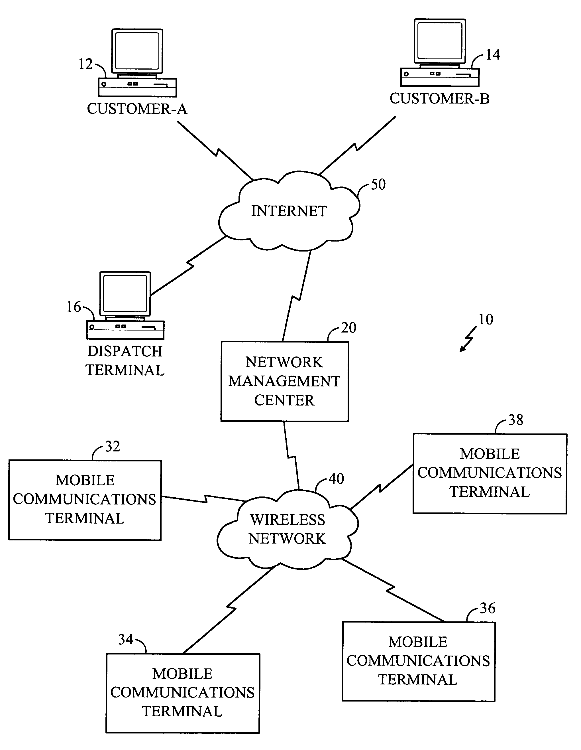
[0016]FIG. 1 is a block diagram of an exemplary wide area network, in particular, a mobile communications architecture 10 in which the present invention may be employed. The architecture 10 includes a network management center (“NMC”) system 20 coupled to a plurality of terrestrial mobile communication terminals (“MCT”) 32, 34, 36, and 38 via a wireless network 40. The wireless network 40 may comprise a satellite network, cellular telephone network, or other wireless voice and / or data communication network. An MCT may be mounted in a vehicle or be part of a mobile device optimally geographically located within the operational boundaries of the wireless network 40.

[0017]The NMC 20 acts as a central routing station for communications between MCTs and one or more customers, shown in FIG. 1 as customer-A 12, customer-B 14, and dispatch terminal 16. The NMC 20 may be coupled to the customer systems 12, 14 and dispatch station 16 by dialup connection, Internet connection 50, or direct con...


PUM


Abstract

A system and method for determining a signal propagation delay between a transmitter and a receiver, and for adjusting a transmission time based on the propagation delay. A central station inserts a marker into a transmitted signal at a time corresponding to a received timing signal. The MCT receives the signal from the central station and determines a time difference between receipt of the marker and the detection of the time interval event. A transmission by the MCT is adjusted by an amount of time proportional to the time difference.

Description

BACKGROUND OF THE INVENTION[0001]I. Field of the Invention[0002]The invention relates to wireless communications and, in particular, to determining a propagation delay between a transmitter and a receiver.[0003]II. Description of the Related Art[0004]In wireless communication networks, the signal transmission propagation delay between a transmitter and a receiver may vary greatly. When such units communicate randomly in these networks, signal detection / synchronization may be difficult, requiring a receiver to search over a wide range of frequencies, times, codes, etc. and employ significant resources to complete random signal reception synchronization. Additionally, significant link overhead is required to enable successful demodulation. A need thus exists for a method and apparatus that reduces the random signal detection / synchronization complexity.SUMMARY OF THE INVENTION[0005]The present invention comprises methods and apparatus for determining a signal propagation delay between ...

Claims


Application Information

Patent Timeline
IPC IPC(8): H04B17/00H04B7/00H04B7/26H04J3/06H04J13/00H04L7/08
CPCH04J3/0682H04W56/0045H04W56/0085H04J3/0644H04L7/08
Inventor ERLENBACH, JUDDGUTTERMAN, FRANKLIN J.TIAN, BIN
Owner OMNITRACS
Why Eureka
Try Eureka