Method and apparatus for automatically testing a railroad interlocking

a technology of automatic testing and interlocking, applied in the field of automatic testing of railroad signal system interlocking or control point, can solve the problems of changing signal aspects, changing any approach signal to a restrictive state, and more complex interlockings implemented

Inactive Publication Date: 2008-04-22
ULTRA TECH ENTERPRISES
View PDF1 Cites 20 Cited by
  • Summary
  • Abstract
  • Description
  • Claims
  • Application Information

AI Technical Summary

Problems solved by technology

However, in areas where additional tracks are involved or multiple routes intersect, more complex interlockings are implemented as required by the track configurations and the routing requirements.
Some unsafe conditions that are prevented by the design and implementation of the interlocking plant are throwing a switch while a train is passing over the switch (causes a derailment), switching a train onto another track occupied by another train (causes a head on or rear end collision), or throwing a switch in front of a moving train that had previously been cleared to proceed and is now unable to stop in time when the signal or switch position becomes visible to the engineer.
In addition, other unsafe conditions are monitored and can cause signal aspects to change to less permissive or even restrictive indications when they are detected.
A hand switch that is manually thrown, usually to permit a switching engine to operate on the track, presents an obstruction or derailment possibility, and changes any approach signal to a restrictive state.
Since there are many thousands of these interlocking plants situated along the railroads, considerable time, labor, and cost are dedicated to meeting these testing requirements.
This means that the dispatcher has given up control of the interlocking for the duration of the tests.
The consequence of this interruption in service is unwanted train delays and possible loss of revenue.
If the train still occupies the block(s) between the interlockings, then the signal may be restrictive.
These tests are complex and exhaustive.
The realities of railroad operation may not allow sufficiently long blocks of track time to fully test an interlocking without releasing track time and allowing a train to pass through an operational interlocking.
This presents an opportunity for misunderstood commands and requests, erroneous reporting of results, and the need to repeat commands and steps until the test has been correctly performed.

Method used


Image

  • Method and apparatus for automatically testing a railroad interlocking
  • Method and apparatus for automatically testing a railroad interlocking
  • Method and apparatus for automatically testing a railroad interlocking

Examples


Embodiment Construction

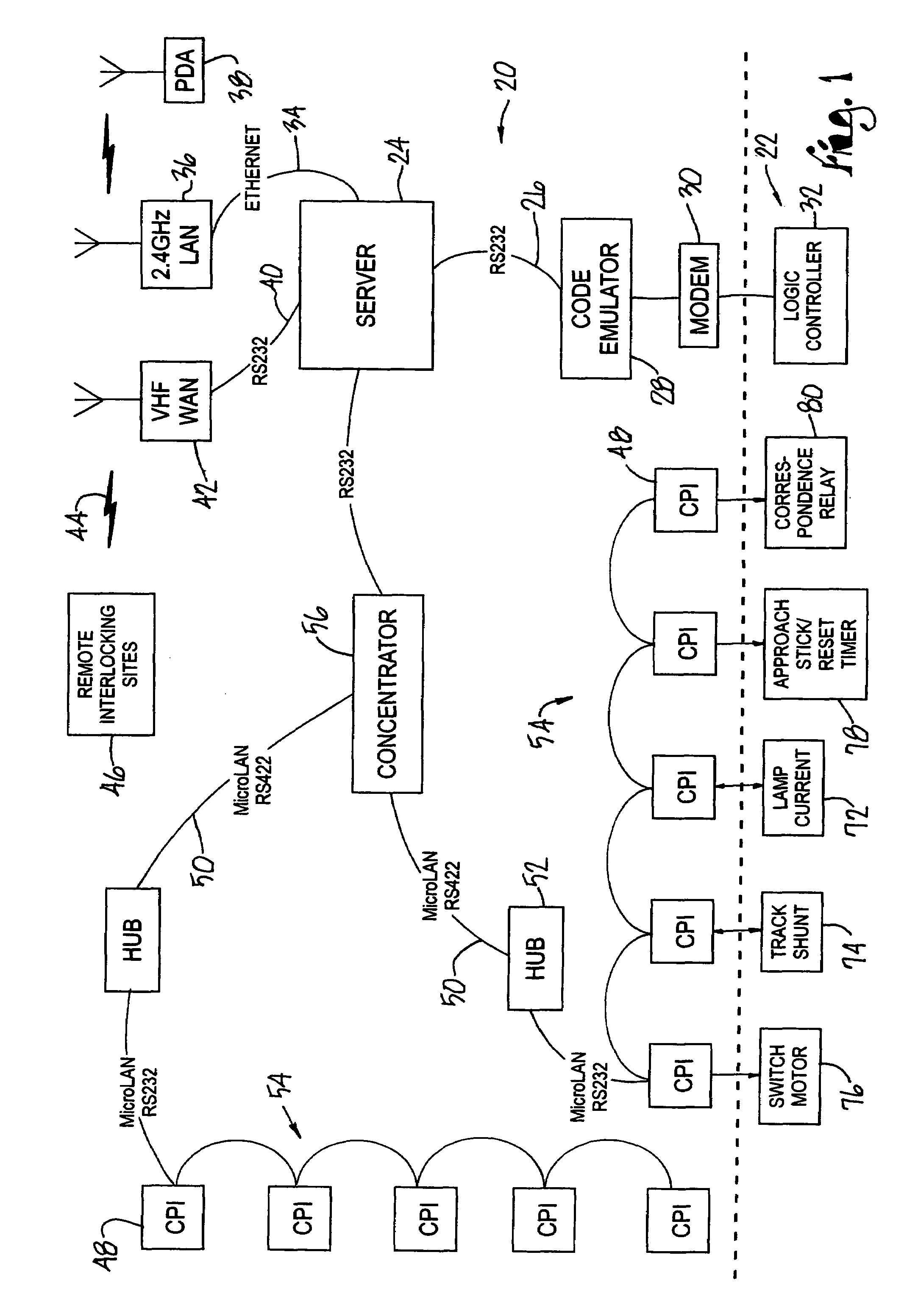
[0040]The system hardware configuration is set forth below followed by the methodology used to capture the design and execute the testing. FIG. 1 illustrates the system equipment 20 deployed at an interlocking under test 22. A server 24, which may be a laptop computer equipped with the necessary interfaces, hosts the software and controls the execution of the test. Commands to the interlocking under test 22 are sent via an RS-252 serial port 26. A code emulator interface unit 28 converts this information to the format required by the specific equipment in the interlocking under test 22. Several different code emulators may be employed to interface with legacy equipment. Alternatively, multiple interfaces may be implemented in a single code emulator 28. The output interface of the code emulator is a modem 30 connected to a logic controller 32 that is part of the interlocking plant. Indications from the logic controller 32 are also read back by the server 24. This interface replaces t...


PUM


Abstract

A railroad signal system interlocking is automatically tested. A control point interface corresponding to a predetermined function of the interlocking has an isolated section and a control section. The isolated section is connected with the interlocking and has a normal, inactivated state during operation of the interlocking, and an activated state for testing the interlocking by detecting an electrical characteristic representing the status of the predetermined function executed by the interlocking. The control section drives the isolated section to its activated state and receiving an output from the isolated section in response to the detected electrical characteristic, and delivers a status report.

Description

CROSS REFERENCE TO RELATED APPLICATIONS[0001]This application claims the benefit of prior filed, co-pending Ser. No. 60 / 586,474, filed Jul. 8, 2004, entitled METHOD AND APPARATUS FOR AUTOMATICALLY TESTING A RAILROAD INTERLOCKING.FIELD OF THE INVENTION[0002]The present invention relates to railroad signal systems, and more particularly, to a method and system for automatically testing a railroad signal system interlocking or control point.BACKGROUND OF THE INVENTION[0003]Railroad signal system interlockings or control points are periodically tested to ensure that they are fully functional. An interlocking is a collection of electrical and electronic assemblies including but not limited to relays, logic controllers, signal lamps, switch motors, timers, coding and decoding units, modems, and other miscellaneous components and connections. The purpose of the interlocking is to control and monitor a railroad control point such as an end or siding, crossover, or double crossover.[0004]An ...

Claims


Application Information

Patent Timeline
Patent Type & Authority Patents(United States)
IPC IPC(8): G06F19/00G01M99/00
CPCB61L21/04B61L27/0055B61L27/60
Inventor WINKLER, JOSEPH C.GALBURT, PAUL J.CROSBY, DONALD P.RAYNA, DAVID K.TRAYNOR, CHRISTOPHER V.BRIECHLE, GEORGE T.
Owner ULTRA TECH ENTERPRISES
Why Eureka
Try Eureka