

Multiplexed digital assays with combinatorial use of signals
a technology of combinatorial use and multi-channel assays, applied in the field of multi-channel digital assays with combinatorial use of signals, can solve the problems of increasing the cost of instrumentation with more detection channels, increasing the number of distinguishable dyes, and becoming impractical beyond
- Summary
- Abstract
- Description
- Claims
- Application Information
AI Technical Summary
Benefits of technology
Problems solved by technology
Method used
Image

Examples
example 1
Digital Amplification Assays with Dedicated Signals and Composite Signals
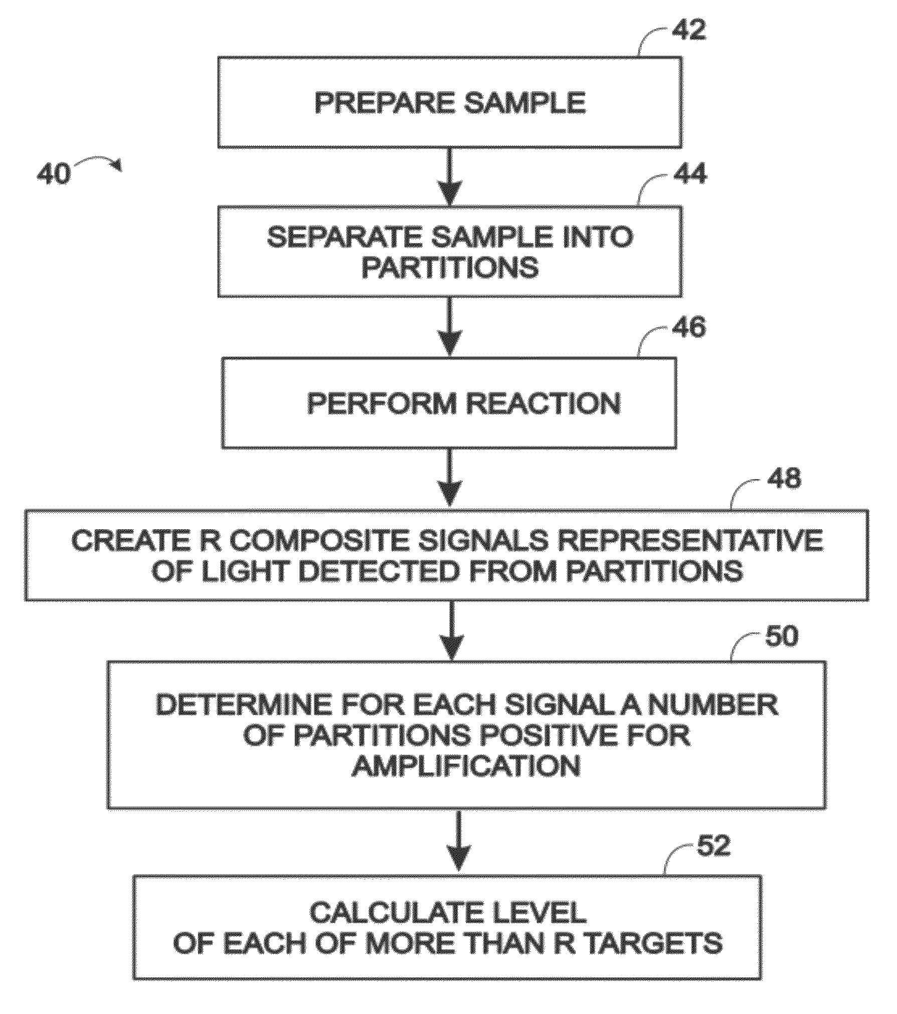
[0065]This example compares and contrasts exemplary digital amplification assays utilizing (i) a pair of dedicated signals for two targets, see FIGS. 3-5, and (ii) a pair of composite signals for three targets, see FIGS. 6-8. The principles explained here may be extended to R signals for 2R−1 targets.
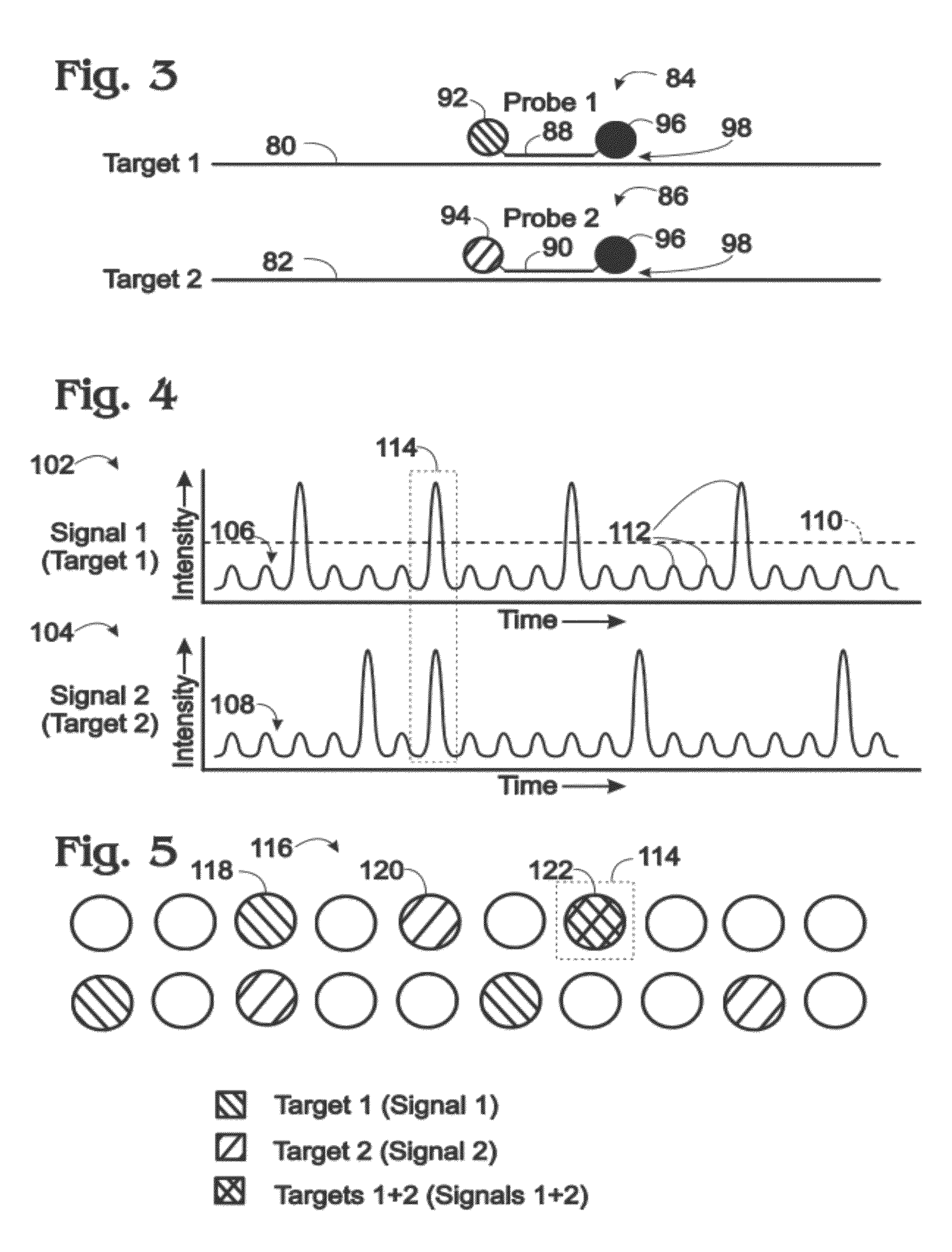
[0066]FIG. 3 shows a pair of nucleic acid targets 80, 82 (“Target 1” and “Target 2”) and corresponding probes 84, 86 (“Probe 1” and “Probe 2”) that may be used to create a dedicated signal for amplification of each target in a digital amplification assay. Each probe may include an oligonucleotide 88, 90, a fluorophore 92, 94, and a quencher 96. The fluorophore(s) and quencher are associated with and / or attached to the oligonucleotide, such as attached covalently. The probe also or alternatively may include a binding moiety (a minor groove binder) for the minor groove of a DNA duplex, which may be conjugated to the ...
example 2
Exemplary Target-Specific Probes for Composite Signals
[0081]This example describes additional, exemplary target-specific probes that may be utilized in any suitable multiplexed digital assay; see FIGS. 9A, 9B, and 10. The principles explained here may be extended to any number of signals and / or targets.
[0082]FIGS. 9A, 9B, and 10 shows third target 140 of FIG. 6 and other exemplary probe configurations of probes 180, 182 (Probes 3A and 3B) each specific for Target 3 (and / or an amplicon thereof). Probes 3A and 3B may be used together, in place of Probe 3 of FIG. 6, and in conjunction with Probe 1 and Probe 2 of FIG. 6, to create only a pair of composite signals for Targets 1 to 3 in a digital amplification assay.
[0083]One of the probes (e.g., Probe 3A) may include fluorophore 92 and the other probe (e.g., Probe 3B) may include fluorophore 94. Accordingly, light emitted by Probe 3A can be detected in the same detection channel as light from Probe 1 of FIG. 6, and light emitted by Probe...
example 3
Exemplary Tailed Primers and Shared Probes for Composite Signals
[0086]This example describes exemplary shared probes that enable creation of composite signals, and exemplary tailed primers forming binding sites for the shared probes; see FIG. 11. The principles explained here may be extended to any suitable number of composite signals and / or targets.
[0087]FIG. 11 shows three targets 80, 82, and 140 (i.e., Targets 1 to 3 of FIG. 6) and corresponding primers that enable assay of the three targets with only two probes, namely, probe 190 (Probe A) and probe 192 (Probe B), in a digital amplification assay. Probe A and Probe B may include respective fluorophores and a quencher (e.g., see FIG. 3).
[0088]Target 1 may be amplified with a pair of forward and reverse primers 194, 196. Forward primer 194 may be a tailed primer with a 3′ binding portion 198 that is complementary to a region of Target 1 and a 5′ tail portion 200 that is not. The tail portion may introduce a binding site for Probe ...
PUM
| Property | Measurement | Unit |
|---|---|---|
| Concentration | aaaaa | aaaaa |
| Wavelength | aaaaa | aaaaa |
| Energy | aaaaa | aaaaa |
Abstract
Description
Claims
Application Information