
Fall arrest safety anchorage device

a safety anchorage and safety technology, applied in safety belts, machine supports, building scaffolds, etc., can solve the problems of difficult manufacture and installation of many existing fall arrest safety anchorage devices, and the securing is not easy to be reversed

Inactive Publication Date: 2008-04-29
DRUMMOND BRUCE ALAN
View PDF3 Cites 6 Cited by
  • Summary
  • Abstract
  • Description
  • Claims
  • Application Information

AI Technical Summary

Benefits of technology

"The present invention is a versatile fall arrest safety anchorage device that can be used for horizontal and vertical lifeline attachment and other fall arrest safety equipment attachment. It can be mounted in different ways and can be secured to a wide variety of rigid planar substrates. The device meets all Occupational Safety and Health Administration regulations and can remain in place until a substantial amount of work or service is performed. It is easy to install and remove, has a high degree of strength, and can be reused after previous installation. The device can be manufactured easily and inexpensively."

Problems solved by technology

Falls are the number one cause of fatalities in the construction industry.
A wide variety of fall arrest safety anchorage devices have been made in an attempt to provide fall protection safety for construction workers, however there are several problems with the fall arrest safety anchorage devices that are readily available.
Another common problem lies in the versatility of securing the fall arrest safety anchorage devices.
Besides the previously mentioned problems, many of the existing fall arrest safety anchorage devices are difficult to manufacture and install.

Method used


Image

  • Fall arrest safety anchorage device
  • Fall arrest safety anchorage device
  • Fall arrest safety anchorage device

Examples


Embodiment Construction

[0028]In the following description, like parts are marked throughout the specification and drawing figures with the same reference numerals, respectively. The drawing figures are not necessarily to scale and certain features may be shown in somewhat a generalized form in the interest of clarity.

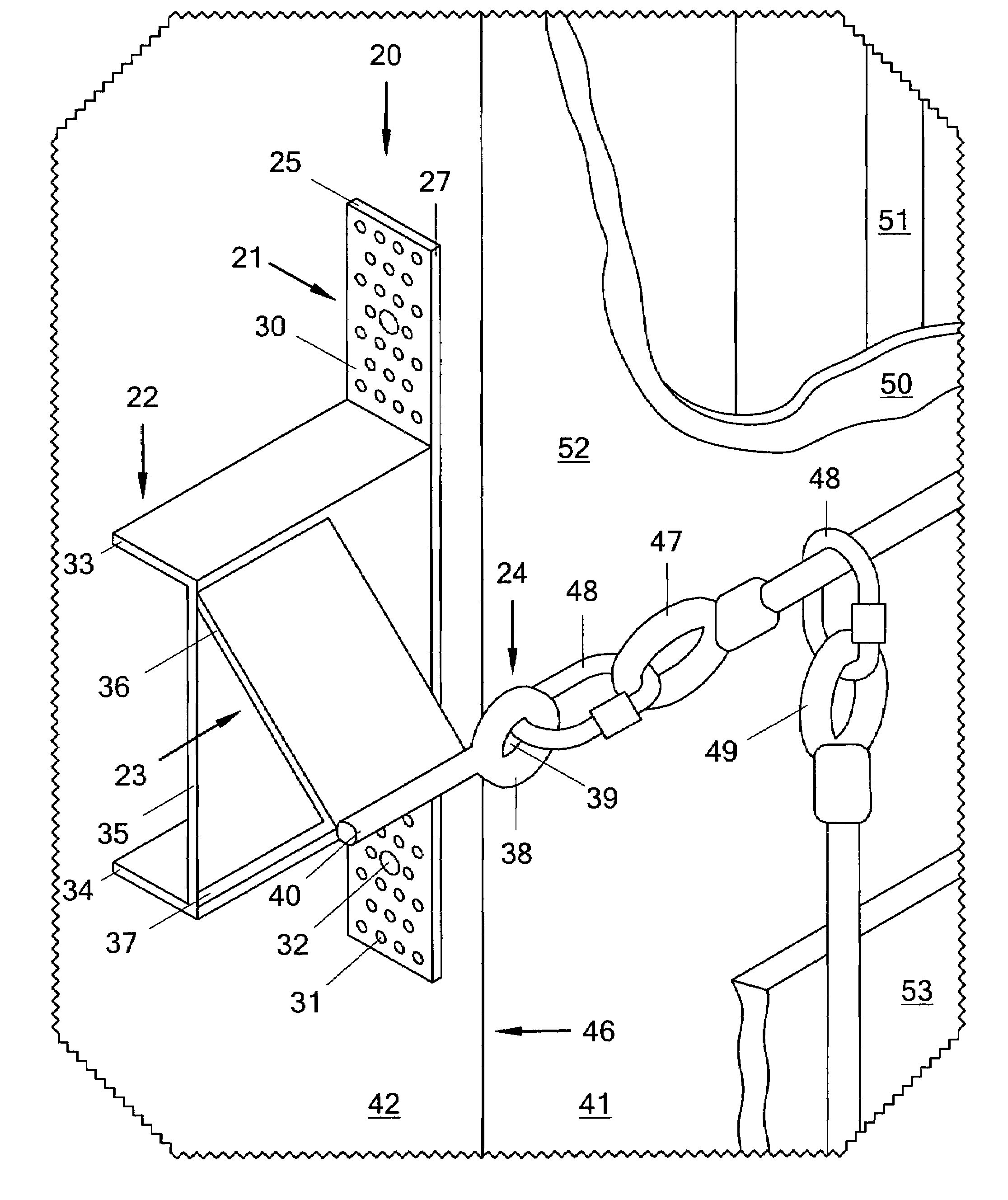
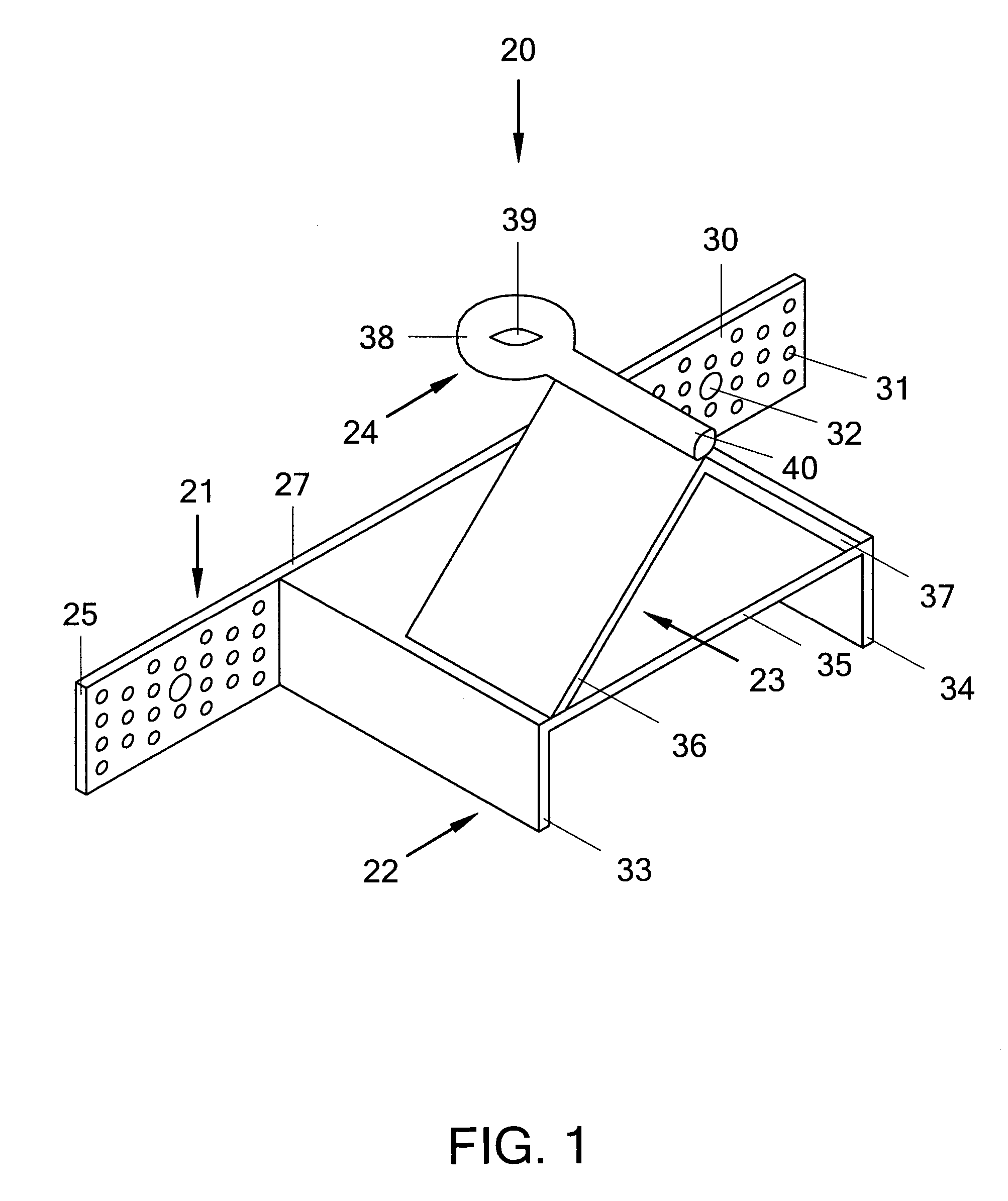
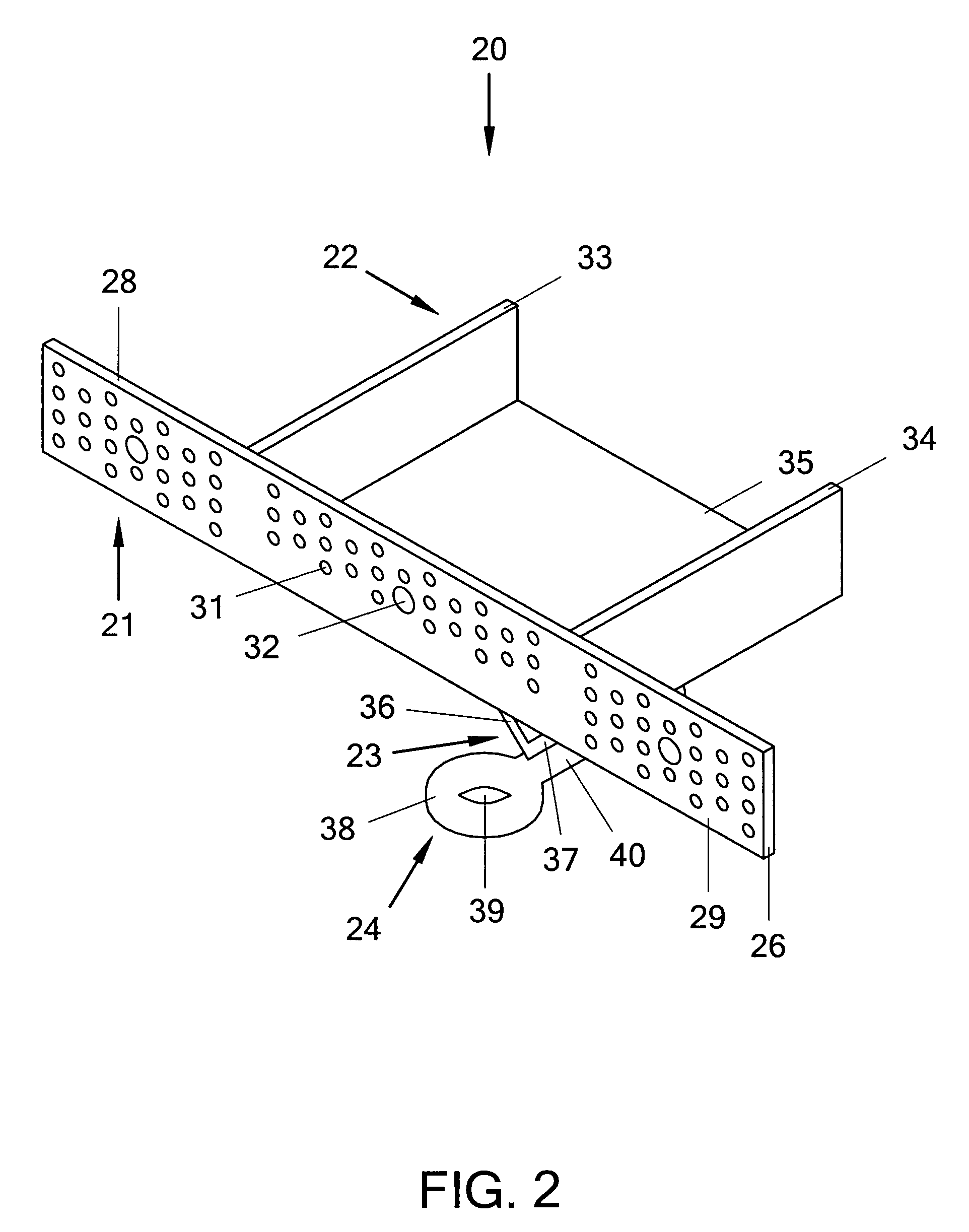
[0029]Referring now to FIG. 1 and FIG. 2, there is shown a fall arrest safety anchorage device constructed according to the teachings of the present invention, the fall arrest safety anchorage device being generally indicated by the reference numeral 20. As will be described further in detail below, the fall arrest safety anchorage device 20 is designed for use in receiving and securing fall arrest safety equipment.

[0030]It should be noted that the Occupational Safety and Health Administration standard 1926.502 (Year of 2004) stipulates that anchorages used for the attachment of personal fall arrest equipment shall be capable of supporting at least five thousand pounds per employee attached a...


PUM


Abstract

A fall arrest safety anchorage device, which can be mounted to a wide variety of rigid planar substrates by utilizing fasteners which pass through apertures in a mounting plate and into a substrate. Angularly extending from the mounting plate is a first positioning member, which projects away from the mounting area to a predetermined position where a second positioning member is attached. The second positioning member angularly extends from the first positioning member to another predetermined position where a safety equipment receiver is attached. Utilizing angles of varying degree at the points of attachment of the positioning members and varying the lengths of the positioning members, the safety equipment receiver can be positioned virtually anywhere. Most important, the safety equipment receiver can be positioned at a desired location away from the initial mounting area for the securing of fall arrest safety equipment, thus providing clearance for the installation of construction materials and allowing workers to perform work safely at heights greater than six feet. Occupational Safety and Health Administration regulations stipulate that whenever a potential for a fall at a height of six feet or more exists, fall protection must be utilized for the safety of workers.

Description

CROSS-REFERENCE TO RELATED APPLICATIONS[0001]Not ApplicableSTATEMENT REGARDING FEDERALLY SPONSORED RESEARCH OR DEVELOPMENT[0002]Not ApplicableREFERENCE TO SEQUENCE LISTING, A TABLE, OR A COMPUTER PROGRAM LISTING COMPACT DISK APPENDIX[0003]Not ApplicableBACKGROUND OF THE INVENTION[0004]The present invention relates generally to construction site safety equipment, and more specifically to a fall arrest safety anchorage device.[0005]Falls are the number one cause of fatalities in the construction industry. Occupational Safety and Health Administration regulations stipulate that whenever a potential for a fall at a height of six feet or more exists, fall protection must be utilized for the safety of workers. There are several types of fall protection permitted for working at heights above six feet, however, a personal fall arrest safety system is the safest. A personal fall arrest safety system generally consists of an anchorage, connectors, and body harness, but may also include a lany...

Claims


Application Information

Patent Timeline
Patent Type & Authority Patents(United States)
IPC IPC(8): A62B35/00
CPCA62B1/04A62B35/0068E04G21/3261E04G21/3276E04G21/3295
Inventor DRUMMOND, BRUCE ALAN
Owner DRUMMOND BRUCE ALAN
Learn More