Seal and retainer for a fluid connection

a fluid connection and seal technology, applied in the direction of sealing, hose connection, cable termination, etc., can solve problems such as complicated problems, and achieve the effect of minimizing marking and efficient and thorough pre-annealing cleaning

Active Publication Date: 2008-04-29
APPLIED ENGINEERED SURFACES
View PDF36 Cites 15 Cited by
  • Summary
  • Abstract
  • Description
  • Claims
  • Application Information

AI Technical Summary

Benefits of technology

[0007]The seal/retainer has an inner diameter IDlegs formed by the radially innermost portions of the retaining legs, and this dimension is not less than the outer diameter ODgasket of the gasket. In this manner, a plurality of the seal/retainer units can be nested in a stacked arrangement. The intersection between the bottom surface of the sealing gasket and the radially inner surface of the leg(s) is a rounded corner (formed during the bending step), which assures a gap G between adjacent seal/retainer units in the nested stack. This gap G allows an efficient and thorough pre-annealing cleaning of the parts, which is essential for subsequent polishing and ultra-cleaning in certain (e.g., semiconductor-related) circumstances.
[0008]Each retaining leg is provided preferably with a rounded (i.e., no sharp angles) distal edge. The rounded distal ed

Problems solved by technology

However, the challenge currently facing the industry, is the production of satisfactorily performing parts in an economic, commercially viable manner.
This challenge is complicated when a fluid connection is int

Method used


Image

  • Seal and retainer for a fluid connection
  • Seal and retainer for a fluid connection
  • Seal and retainer for a fluid connection

Examples


Embodiment Construction

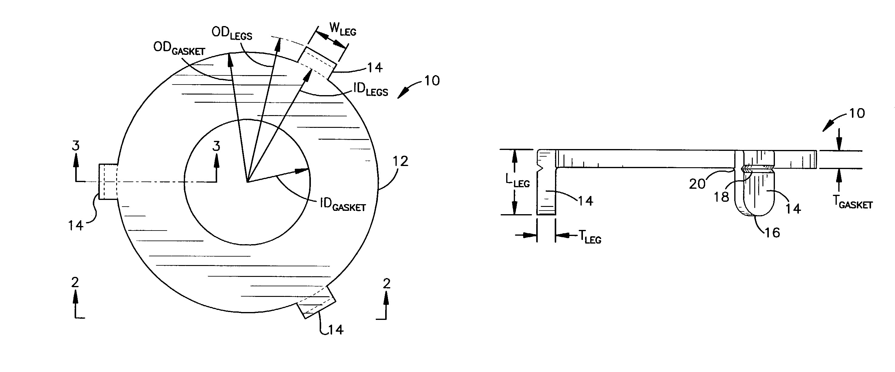
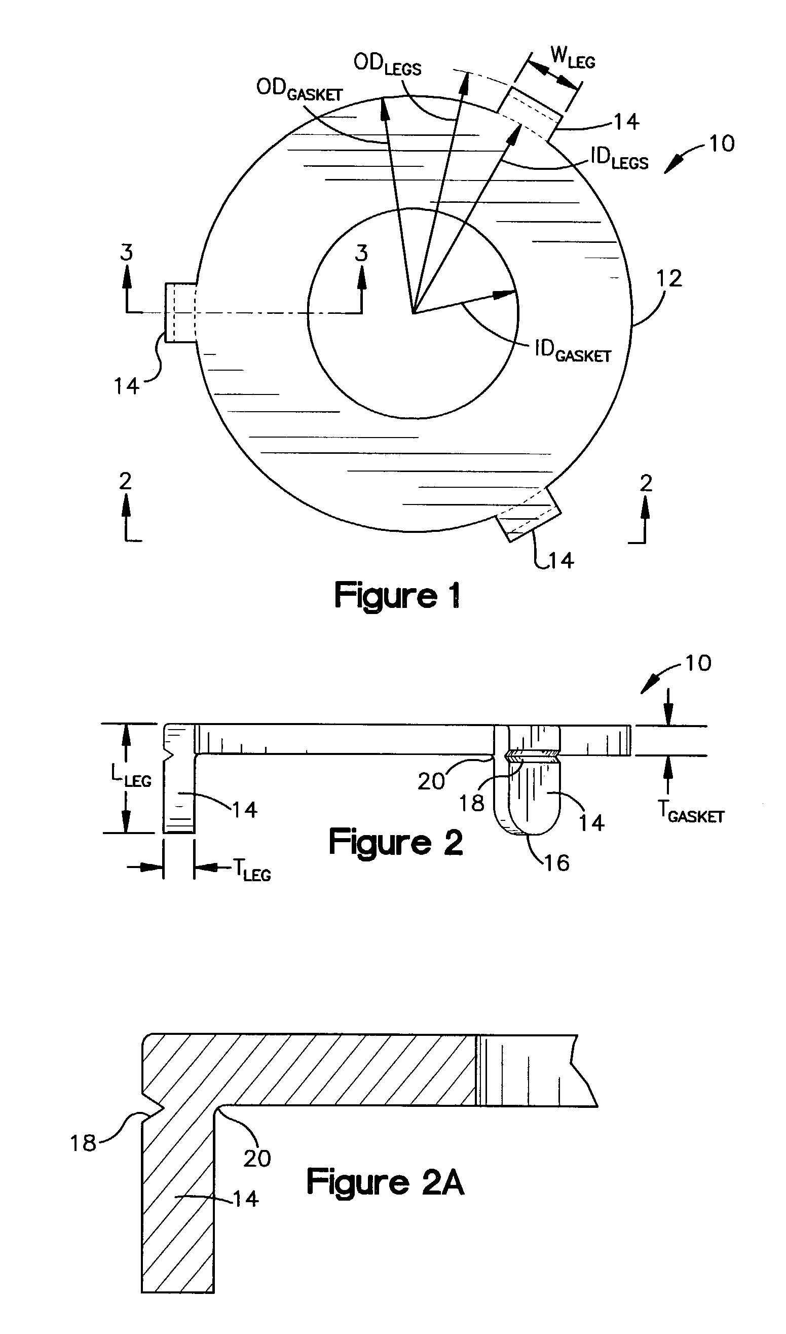
[0022]Referring now to the drawings in detail, and initially to FIGS. 1 and 2, an integrated seal / retainer 10 according to the present invention is shown. The seal / retainer 10 comprises a gasket 12 and one or more retaining legs 14 extending therefrom. The seal / retainer 10 can be made of a sealing material and, more particularly, a sealing metal such as nickel, steel, or copper (e.g., Nickel 201, 316L Stainless Steel, 316L Silver Plated Stainless Steel, and copper). The seal / retainer unit 10 is an integration of a sealing gasket and gasket-retaining legs into a single one-piece part.

[0023]The gasket 12 has an annular shape with an inner diameter IDgasket, an outer diameter ODgasket, and a thickness Tgasket. Each retaining leg 14 has a roughly rectangular shape with a length Lleg, a width Wleg, and a thickness Tleg. Also, the outer surfaces of the retaining legs 14 together define an outer diameter ODlegs and the inner surfaces of the retaining legs 14 define an inner diameter IDlegs...


PUM


Abstract

A seal/retainer unit (10) comprising an annular sealing gasket (12) and a plurality of retaining legs (14) extending generally perpendicularly therefrom. The sealing gasket (12) and the retaining legs (14) are formed in one piece (e.g., stamped) from a sealing material and dimensioned to allow nesting of a plurality of seal/retainer units (10) in a stacked arrangement. The retaining legs (14) may each include a rounded distal edge (16) to minimize package-tearing and interpart-marking and/or a break-off notch (18) to allow special customization. A radiused corner (20) between the gasket (12) and the legs (14) assures a gap between nested parts.

Description

FIELD OF THE INVENTION[0001]This invention relates generally as indicated to a seal and retainer for a fluid connection and, more particularly, to a seal and retainer for a fluid connection comprising a first coupling component, a second coupling component, and a coupling nut which draws the coupling components together.BACKGROUND OF THE INVENTION[0002]A common fluid connection comprises a first coupling component, a second coupling component, and a coupling nut which draws the coupling components together. The inner faces of the first and second coupling components are disposed in an end-to-end relationship to provide a through-path between the respective passageways. A sealing bead extends axially outward from the inner face of the first coupling component and a similar sealing bead extends axially outward from the inner face of the second coupling component. A sealing gasket is interposed between the beads, and seals the union between the first and second coupling components.[000...

Claims


Application Information

Patent Timeline
IPC IPC(8): F16L19/00F16L19/02
CPCF16L19/0218Y10S277/917
Inventor YOAKAM, JOHN ARTHURQUAYLE, RICHARD ALANQUAYLE, DENNIS FLOYD
Owner APPLIED ENGINEERED SURFACES
Why Eureka
Try Eureka