
Surface Profile Measuring Instrument and Method

Pending Publication Date: 2020-09-03
ELCOMETER
View PDF4 Cites 2 Cited by
  • Summary
  • Abstract
  • Description
  • Claims
  • Application Information

AI Technical Summary

Benefits of technology

The patent describes an electromagnetic probe that can measure the surface profile of a substrate by producing a low-frequency magnetic field. This probe is less sensitive to changes in the conductivity and magnetic permeability of the substrate, resulting in more accurate measurements. It also has a high signal to noise ratio and is less influenced by the substrate's geometry. The probe can measure inconsistent surfaces with a large variation in surface features, providing consistent results over time. The instrument used to measure the surface profile can include a spacer that maintains the probe tip at an optimal distance from the surface, reducing the impact of surface inconsistencies on the measurement. The distance between the probe tip and the substrate can be measured, and this measurement is related to the surface profile. Overall, this patent provides a more reliable and accurate method for measuring the surface profile of substrates.

Problems solved by technology

This technique may be subject to handling issues leading to errors in the measurement.
In addition, there is no automatic electronic record of the measurement.
Such instruments are highly susceptible to vibrations, and the needle quickly wears.
In addition, there is no guarantee that the needle reaches the bottom of troughs on the surface.
However, there is no guarantee that the needle will reach the bottom of every trough measured.
Finally, all three techniques are relatively slow when measuring a large surface area.
While this technique speeds up measuring the surface profile of a large surface area (due to the speed involved in generating and measuring a magnetic field in part of a surface) there are still several issues including a high sensitivity to variances in the conductivity and permeability of the substrate material and the geometry of the substrate having a large amount of influence of the generated eddy currents.
The technique therefore has a low signal to noise ratio, which means it is less useful for measuring smoother surfaces with a smaller surface profile measurement value.
Due to the issues noted above, the technique has generally not been adopted to measure surface profile.

Method used


Image

  • Surface Profile Measuring Instrument and Method
  • Surface Profile Measuring Instrument and Method
  • Surface Profile Measuring Instrument and Method

Examples


Embodiment Construction

[0041]In order that the invention may be more clearly understood one or more embodiments thereof will now be described, by way of example only, with reference to the accompanying drawings, of which:

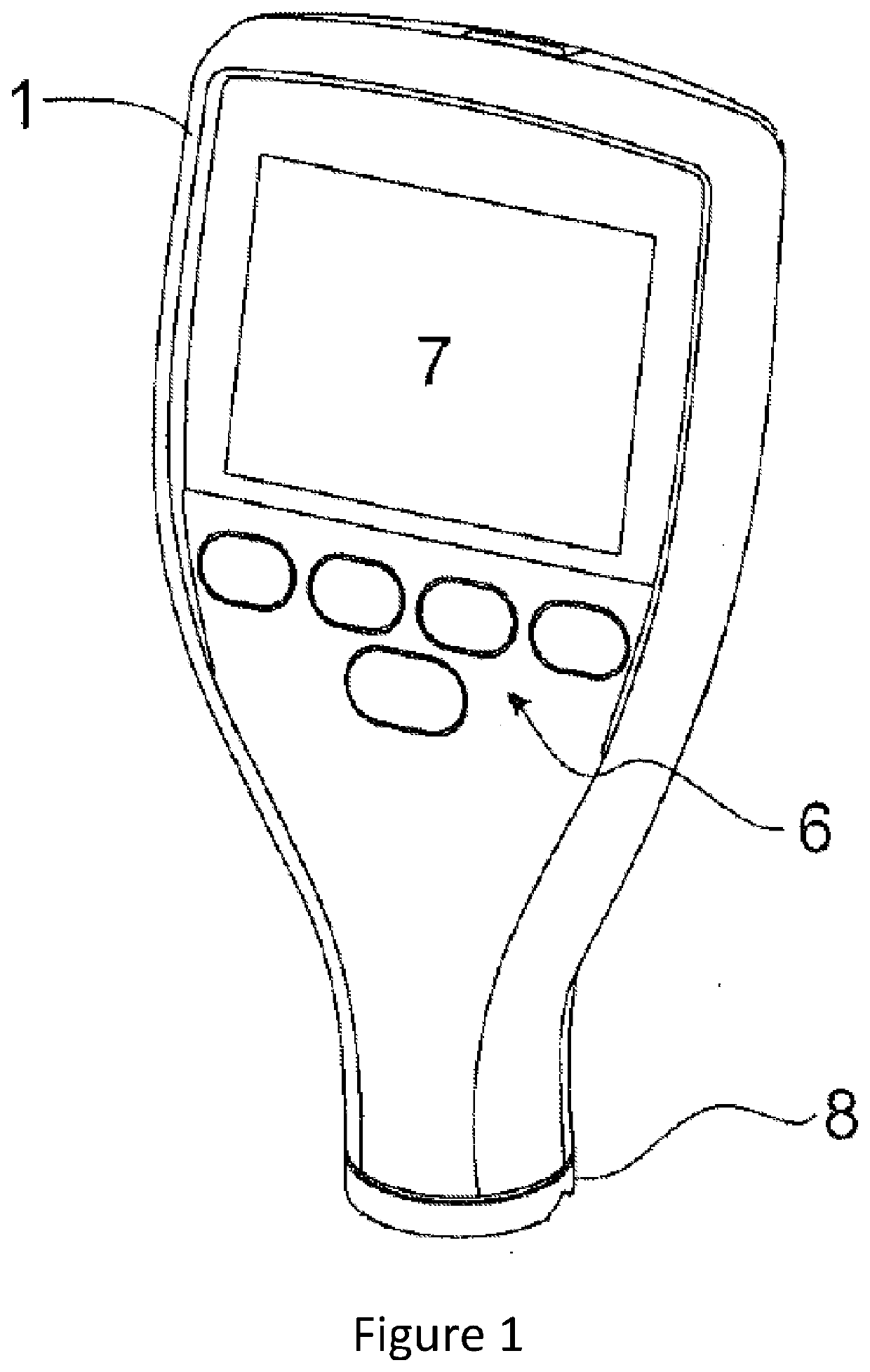
[0042]FIG. 1 shows an embodiment of the surface profile measuring instrument;

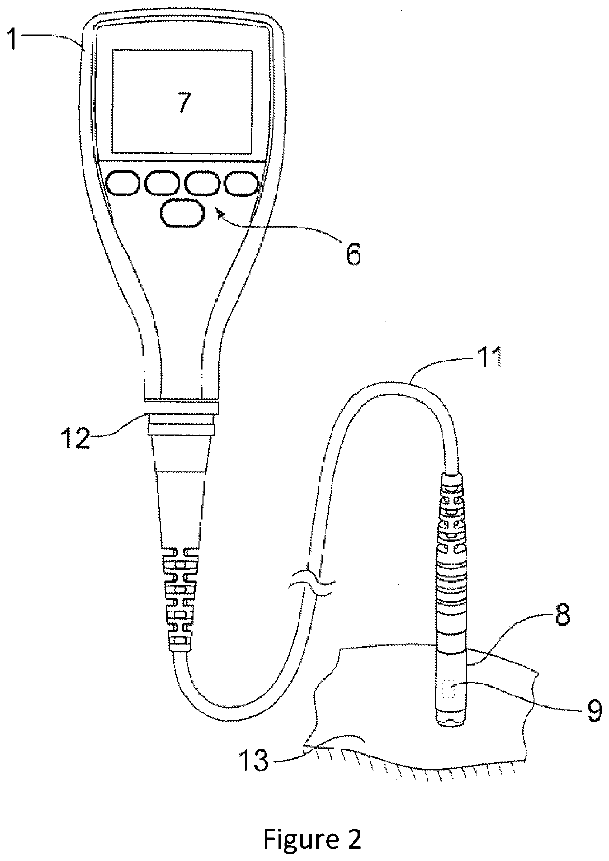
[0043]FIG. 2 shows an alternative embodiment of the surface profile measuring instrument;

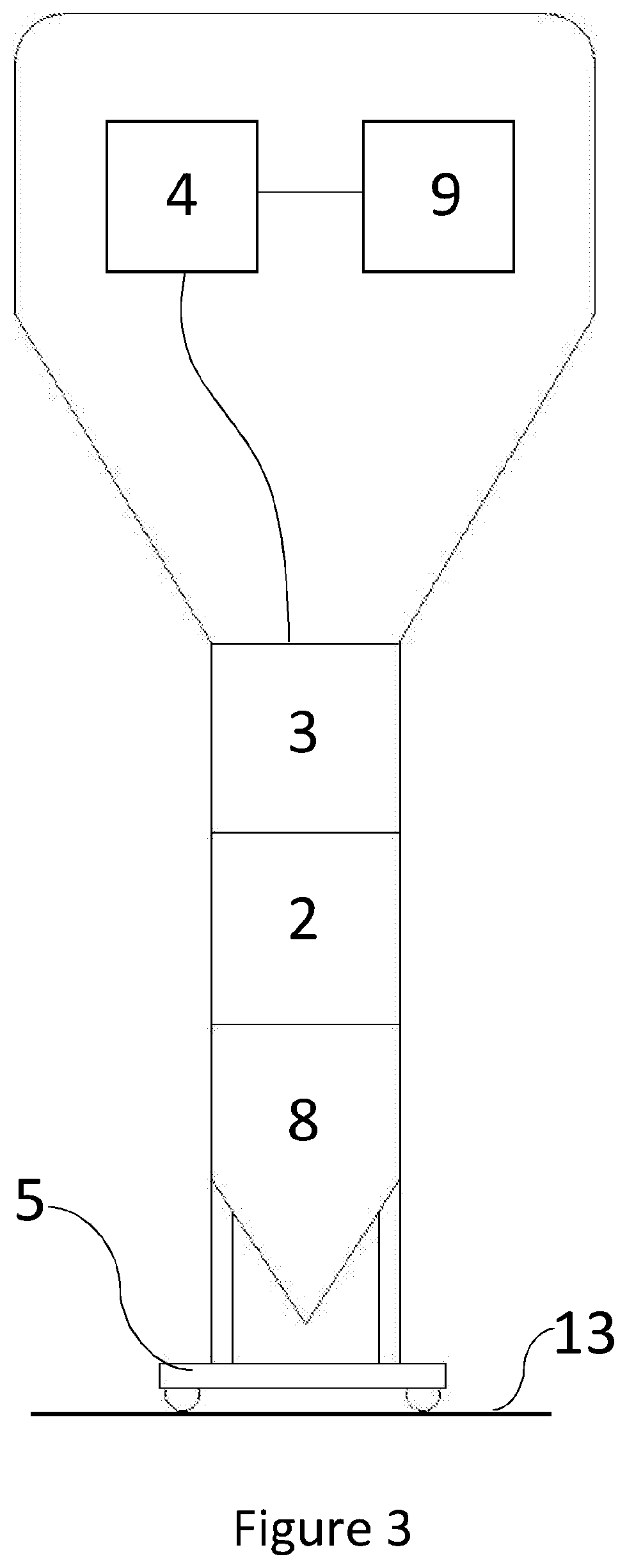
[0044]FIG. 3 shows a further view of the embodiment of the surface profile measuring instrument as shown in FIG. 1;

[0045]FIGS. 4a-c are diagrams demonstrating the response of the surface profile measuring instrument of FIG. 1, 2 or 3 to various substrates;

[0046]FIG. 5 is a graph showing the relationship between probe-surface separation and the coefficient of variation;

[0047]FIG. 6 is a graph showing the relationship between probe-surface separation and the dynamic range; and

[0048]FIG. 7 is a block diagram of how the surface profile measuring instrument of FIG. 1, 2 or 3 generates a surface profile measurement.

[0049]As shown i...


PUM


Abstract

A surface profile measuring instrument (1), and method, for measuring the surface profile of a substrate (13). The surface profile measuring instrument (1) comprises an electromagnetic probe (8), the electromagnetic probe (8) comprising a probe tip operable to be brought into proximity with a surface of a substrate (13) to be measured, a drive unit (2) operable to generate a low frequency magnetic field penetrating the surface of the substrate (13), a pick up unit (3) operable to detect the strength of the magnetic field and output a magnetic field strength reading and a computation unit (4) operable to determine a surface profile measurement based on the magnetic field strength reading.

Description

TECHNICAL FIELD OF THE INVENTION[0001]The present invention relates to a surface profile measuring instrument, and method, for measuring the surface profile of a substrate.BACKGROUND TO THE INVENTION[0002]The surface profile (otherwise known as the surface roughness) of a substrate can dictate many important properties of a substrate, including the friction coefficient of and the ease of adhesion to the substrate. It is therefore useful to determine a measurement of the surface profile of a substrate.[0003]There are several techniques currently used to measure the surface profile of a substrate, all of which have associated disadvantages.[0004]Replica tape involves using compressible foam to obtain an impression of the surface, and then measuring this impression with a micrometer. This technique may be subject to handling issues leading to errors in the measurement. In addition, there is no automatic electronic record of the measurement.[0005]Stylus based instruments drag a fine nee...

Claims


Application Information

Patent Timeline
IPC IPC(8): G01B7/287
CPCG01B7/287G01B7/28G01B7/34
Inventor BENNETT, NEIL JAMES LEONARDBOUIS, JONATHANSELLARS, MICHAEL CARRINGTONPARTINGTON, THOMAS
Owner ELCOMETER
Learn More