
Cassette pigtailing machine for a coil spring

a coil spring and cassette technology, applied in the field of cassette pigtailing machines for coil springs, can solve the problems of reducing manufacturing efficiency, affecting the quality of pigtailing machines, so as to reduce cycle time, minimize marking, and ensure the effect of alignment and proper spring manufacturing

Active Publication Date: 2007-04-03
MERITOR SUSPENSION SYST U S
View PDF22 Cites 1 Cited by
  • Summary
  • Abstract
  • Description
  • Claims
  • Application Information

AI Technical Summary

Benefits of technology

"The present invention is a pigtailing machine that can make a double pigtail coil spring while reducing cycle time and minimizing marking. It includes an A forming head, a B forming head, a drive system for the B forming head, a base, a support pedestal, and a controller. The B forming head and the pedestal are secured to a cassette base, which is located on the base to make it easy to change over to another double pigtail coil spring type. By fixing the forming head and the support pedestal to the cassette base, alignment and proper manufacture of the spring is ensured. The A forming head can also be mounted on the cassette base. Overall, this invention provides a pigtailing machine and forming approach that can make a double pigtail coil spring while ensuring accuracy and efficiency."

Problems solved by technology

Disadvantageously, setup for conventional pigtailing machines is quite extensive.
The setup time for each spring type increases the overall production cycle time and results in a lower manufacturing efficiency.
Additionally, the adjustable components may shift over time due to the aggressive environment in which a pigtailing machine operates.
Shifting in any of the adjustable supports may result in marking of the spring surface which may lead to a stress concentration and potential early fatigue of the spring during service.

Method used


Image

  • Cassette pigtailing machine for a coil spring
  • Cassette pigtailing machine for a coil spring
  • Cassette pigtailing machine for a coil spring

Examples


Embodiment Construction

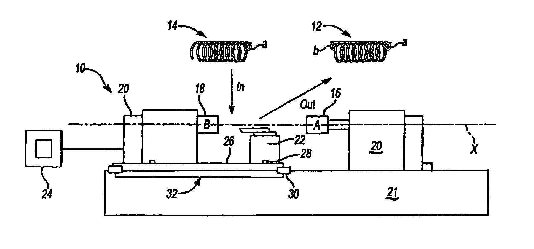
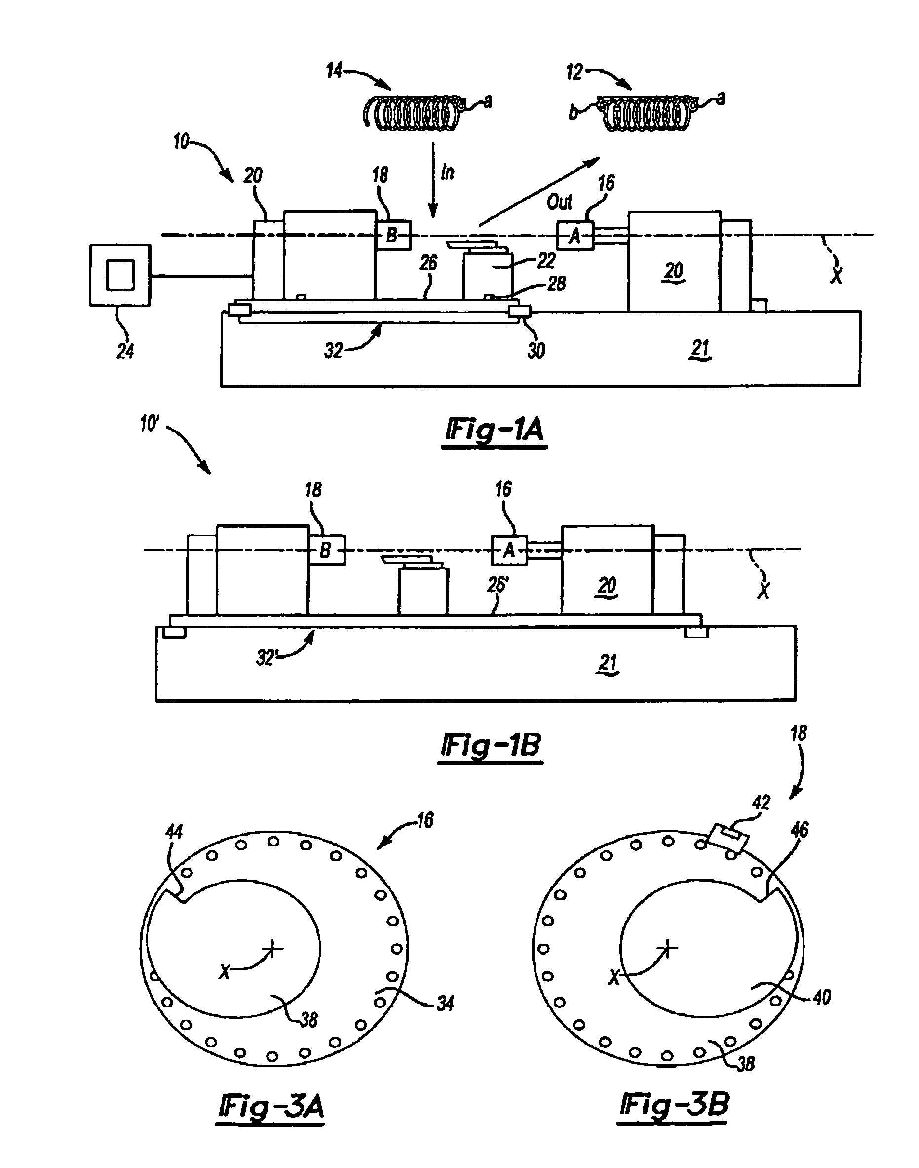
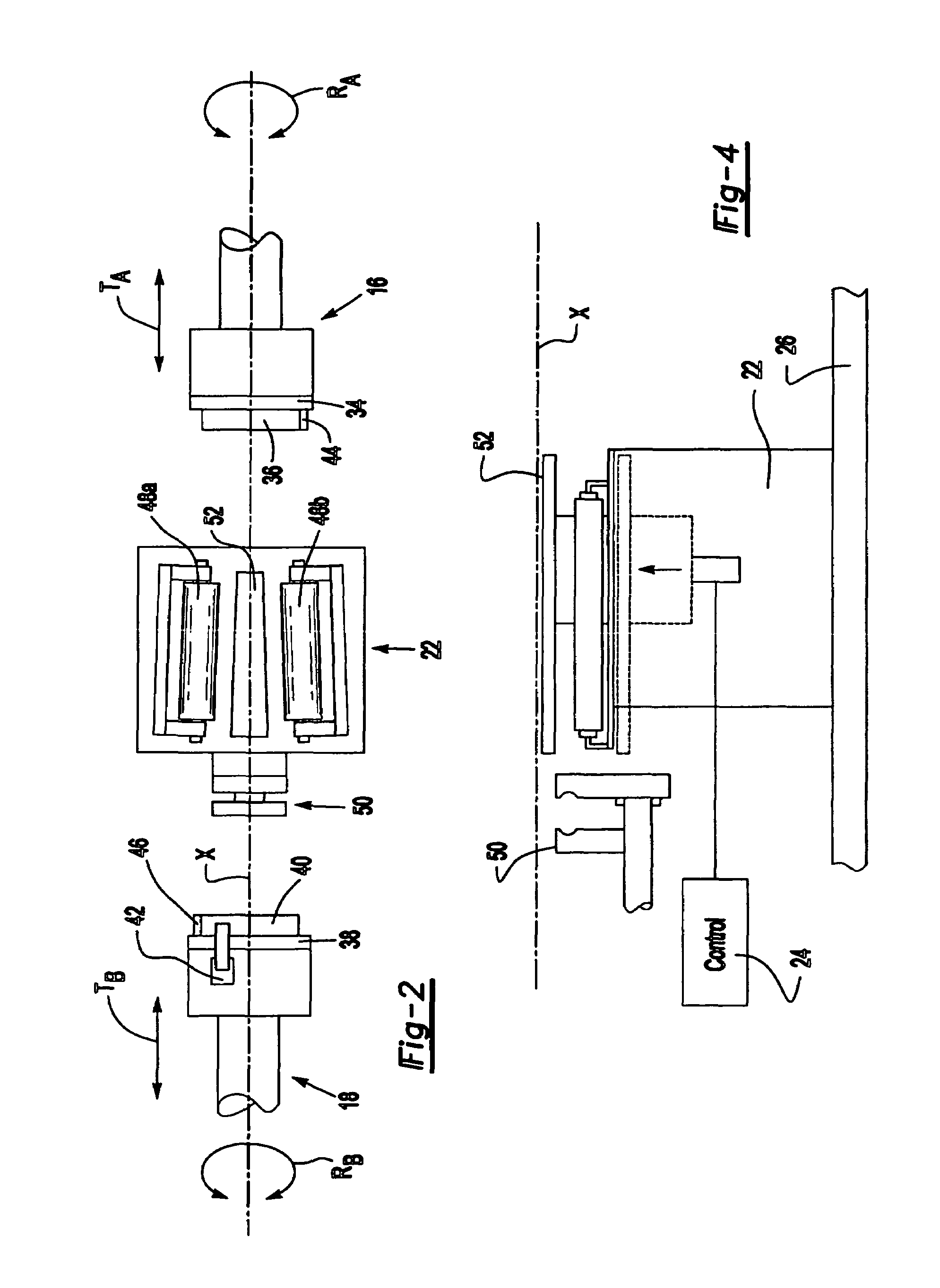
[0017]FIG. 1A illustrates a general schematic view of a pigtailing machine 10 which forms a double pigtailed coil spring 12 which has a pigtail at end a and end b out of a coil spring which has a single pigtail 14 at end a. The pigtailing machine 10 generally includes an A forming head 16, a B forming head 18, a drive system 20 for the B forming head 18, a base 21, a support pedestal 22 and a controller 24 (illustrated schematically).

[0018]Preferably, the B forming head 18, and the pedestal 22 are secured to a cassette base 26 through fasteners 28 such as bolts or the like. The cassette base 26 is located upon the base 21 and locked thereto through locks (illustrated schematically at 30) to provide for a relatively quick changeover should another double pigtail coil spring need be manufactured. That is, a cassette 32 which includes at least the B forming head 18 and the pedestal 22 secured to the cassette base 26 is a dedicated die for the manufacture of a single specific double pig...


PUM

PropertyMeasurementUnit
shapeaaaaaaaaaa
diameteraaaaaaaaaa
sizeaaaaaaaaaa

Abstract

A pigtailing machine includes a B forming head and a support pedestal secured to a cassette base. The cassette base is located upon a base which mounts the A forming head to provide for a relatively quick changeover should another double pigtail coil spring need be manufactured. By fixing the forming head and the support pedestal to the cassette base alignment and proper manufacture of the spring is assured. Alternatively, the A forming head is also mounted to the cassette base.

Description

BACKGROUND OF THE INVENTION[0001]The present invention relates to the forming of a coil spring having pigtails at each end, and more particularly to a machine for efficiently forming the pig tails.[0002]In many instances, it is desirable to have reduced diameter ends or “pigtails” on a wound coil spring. One example application for such springs is in automotive suspension systems. A reduced diameter at one end of the spring can be beneficial for efficiency in spring height and operating travel.[0003]In a typical coil spring forming manufacturing method, a cut-to-length bar is wound around a solid mandrel that sets the inside diameter of the coil spring. One end coil of the spring can be formed smaller than the next coil of the spring using this technique to provide a pigtailed spring. The mandrel for such springs typically has a smaller diameter on one end to form the reduced end of the spring.[0004]It is also beneficial in many circumstances to also reduce the diameter of the oppos...

Claims


Application Information

Patent Timeline
Patent Type & Authority Patents(United States)
IPC IPC(8): B21F35/02B21F3/10
CPCB21F3/10B21F35/02
Inventor DIXON, JEFFREY PAULCOUCH, WAYNE FREDERICK JAMESSEEDS, MARTIN JOHNSINE, THOMAS MARVINGAETAN, OSCARNOVA, TERRENCE JOSEPH
Owner MERITOR SUSPENSION SYST U S
Learn More