CxHy sacrificial layer for cu/low-k interconnects

a technology of low-k dielectrics and sacrificial layers, which is applied in the direction of semiconductor devices, semiconductor/solid-state device details, electrical apparatus, etc., can solve the problems of plasma damage, low-k materials are susceptible to damage, and low-k materials present problems during processing, so as to reduce the damage of low-k dielectrics

Inactive Publication Date: 2008-04-29
TAIWAN SEMICON MFG CO LTD
View PDF24 Cites 10 Cited by
  • Summary
  • Abstract
  • Description
  • Claims
  • Application Information

AI Technical Summary

Benefits of technology

[0009]A preferred embodiment provides a method for forming a semiconductor device having a low-k dielectric. A hydrocarbon layer is deposited on the low-k dielectric. In preferred embodiments, the hydrocarbon layer is deposited using PECVD using a (CH3)2CHC6H6CH3 or C2H4 precursor. Embodiments further comprise forming a recessed feature in the hydrocarbon layer and in the low-k dielectric using a plasma etch. In accordance with embodiments of this invention, carbon diffuses into the low-k dielectric, thereby reducing low-k dielectric damage caused by plasma processing.

Problems solved by technology

However, low-k materials present problems during processing, especially during the processing of the conductive material used to make interconnects.
The low-k materials are susceptible to damage from a plasma etch because they are softer, less chemically stable or more porous, or any combination of these factors.
The plasma damage can manifest itself in higher leakage currents, lower breakdown voltages, and changes in the dielectric constant associated with the low-k dielectric material.
During processing, low-k dielectric surfaces are susceptible to damage.
Porous low-k dielectrics, such as porous silica, are particularly susceptible.
When surface pores are damaged, processing chemicals may penetrate into the dielectric and raise its dielectric constant.
As noted above, dielectric damage causes higher leakage currents, lower breakdown voltages, and changes in the dielectric constant associated with the low-k dielectric material.

Method used


Image

  • CxHy sacrificial layer for cu/low-k interconnects
  • CxHy sacrificial layer for cu/low-k interconnects
  • CxHy sacrificial layer for cu/low-k interconnects

Examples


Embodiment Construction

[0020]The operation and fabrication of the presently preferred embodiments are discussed in detail below. However, the embodiments and examples described herein are not the only applications or uses contemplated for the invention. The specific embodiments discussed are merely illustrative of specific ways to make and use the invention, and do not limit the scope of the invention or the appended claims.

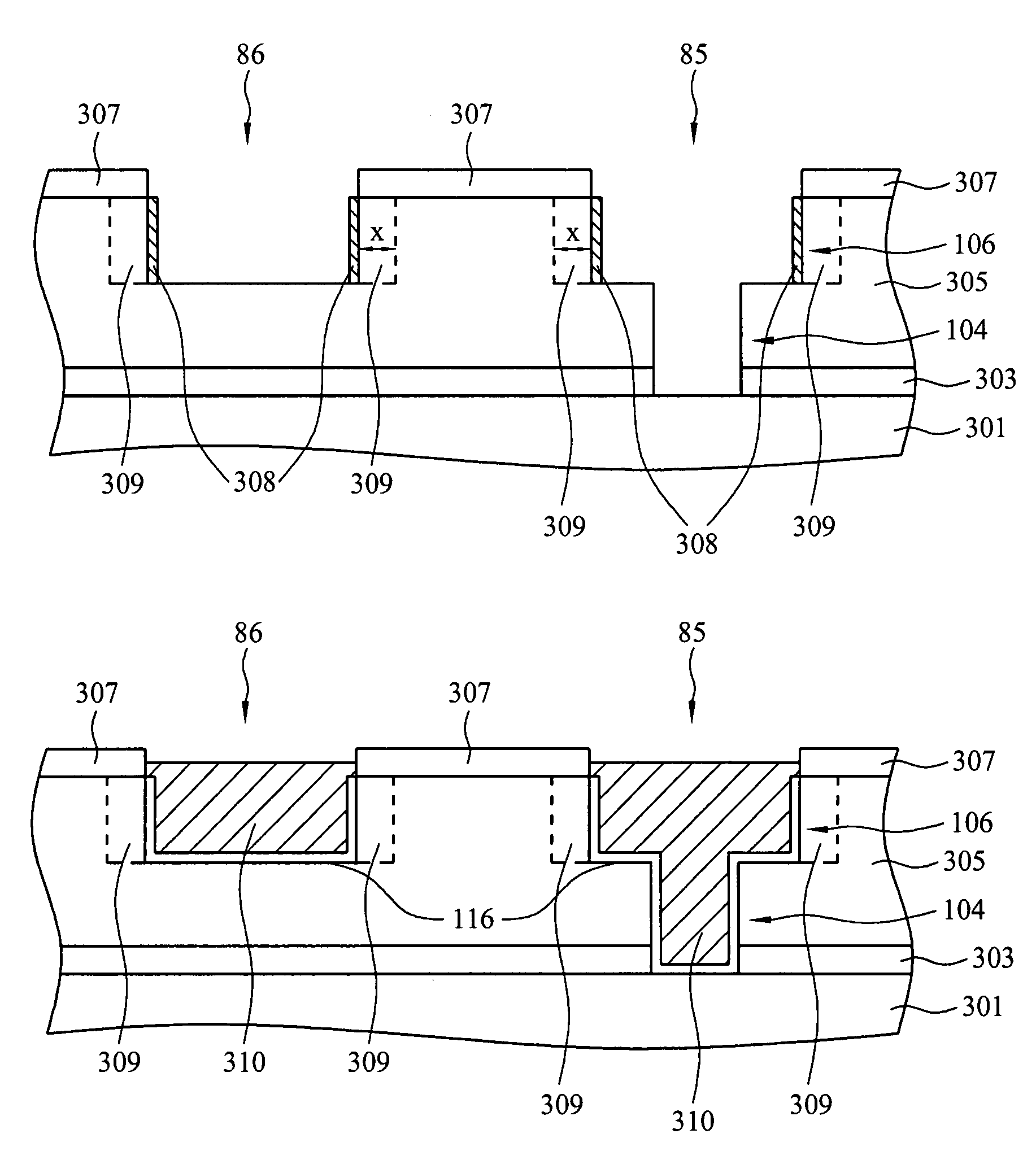
[0021]This invention relates generally to semiconductor device manufacturing and more particularly to the formation and processing of porous, low-k dielectrics. The low-k dielectrics may include films or layers, but embodiments are not limited to these morphologies. The present invention will now be described with respect to preferred embodiments in a specific context, namely the creation of copper conductive lines and vias in the damascene process. It is believed that embodiments of this invention are particularly advantageous when used in this process. It is further believed that emb...


PUM

PropertyMeasurementUnit
temperatureaaaaaaaaaa
pressureaaaaaaaaaa

Abstract

A semiconductor method of manufacturing involving low-k dielectrics is provided. The method includes depositing a hydrocarbon of the general composition CxHy on the surface of a low-k dielectric. The hydrocarbon layer is deposited by reacting a precursor material, preferably C2H4 or (CH3)2CHC6H6CH3, using a PECVD process. In accordance with embodiments of this invention, carbon diffuses into the low-k dielectric, thereby reducing low-k dielectric damage caused by plasma processing or etching. Other embodiments comprise a semiconductor device having a low-k dielectric, wherein the low-k dielectric has carbon-adjusted dielectric region adjacent a trench sidewall and a bulk dielectric region. In preferred embodiments, the carbon-adjusted dielectric region has a carbon concentration not more than about 5% less than in the bulk dielectric region.

Description

CROSS-REFERENCE TO RELATED APPLICATIONS[0001]This application related to co-pending and commonly assigned patent application Ser. No. 11 / 048,518 (TSM04-08 16), filed concurrently herewith, entitled “Sealing Pores of Low-K Dielectrics Using CxHy.” This application also relates to co-pending and commonly assigned patent application Ser. No. 10 / 985,149 (TSM04-0369), filed Nov. 10, 2004, entitled “Diffusion Barrier for Damascene Structures.” These co-pending and commonly assigned patent applications are hereby incorporated by reference.TECHNICAL FIELD[0002]This invention relates to semiconductor manufacture and more particularly to improved methods for forming devices having low-k dielectrics.BACKGROUND[0003]As the density of semiconductor devices increases and the size of circuit elements becomes smaller, the resistance capacitance (RC) delay time increasingly dominates the circuit performance. To reduce the RC delay, there is a desire to switch from conventional dielectrics to low-k d...

Claims


Application Information

Patent Timeline
Patent Type & Authority Patents(United States)
IPC IPC(8): H01L21/469H01L23/58
CPCH01L21/312H01L21/76802H01L21/76807H01L21/76829H01L21/76831H01L21/02118H01L21/0212H01L21/02126H01L21/02129H01L21/02131H01L21/02134H01L21/02137H01L21/02203H01L21/02274
Inventor JENG, SHWANG-MINGYEH, MING LINGBAO, TIEN-ILIN, KENG-CHU
Owner TAIWAN SEMICON MFG CO LTD
Why Eureka
Try Eureka