Discharge lamp ignition device and projector

a technology of ignition device and discharge lamp, which is applied in the direction of electric variable regulation, process and machine control, instruments, etc., can solve the problems of complicating the control of space modulation element in the projector equipment, and reducing the effective efficiency of light beam, so as to reduce the effect of excessive phenomena, smooth out the changes, and simplify the process

Active Publication Date: 2008-04-29
USHIO DENKI KK
View PDF7 Cites 15 Cited by
  • Summary
  • Abstract
  • Description
  • Claims
  • Application Information

AI Technical Summary

Benefits of technology

[0032]With the invention, at least during steady operation of the discharge lamp, the target lamp current signal generation circuit acquires multiple lamp voltage detection signals over a period at least as long as the color order cycle of the dynamic color filter and then generates the target lamp current signal on the basis of the multiple lamp voltage detection signals that were acquired. The lamp voltage information that is referenced in order to generate the target lamp current signal is indifferent to the amount of modulation of the lamp voltage corresponding to the returning light spectrum, and as a result, it is possible to provide a discharge lamp ignition device that succeeds in avoiding the phenomenon of unsightly flickering of images projected by the projector, even in the presence of the phenomenon of cyclical modulation of the lamp voltage by the returning light spectrum when light reflected by the dynamic color filter returns back through the optical system to the lamp.
[0033]When the target lamp current signal is generated, the operation of refreshing the target lamp current signal begins intermittently while waiting for a period at least as long as the color order cycle of the dynamic color filter and the previously refreshed value is stored during the period until the value is again refreshed, and as a result, it is possible to provide a discharge lamp ignition device that succeeds in simplifying processes by reducing the frequency of generation of target lamp current detection signals.
[0034]At the time of the refreshing operation, there is a gradual change from the stored value to the refreshed value, and as a result, it is possible to provide a discharge lamp ignition device that succeeds in stopping abrupt changes in lamp brightness and smoothing out the changes, even when there is a discrepancy between the target lamp current signal that has been decided and the target lamp current signal that was decided in the previous refresh operation.
[0035]When the lamp voltage detection signal is acquired, the lamp voltage detection signal is acquired in synchronization with the timing of polarity reversal by the inverter, so that the lamp voltage detection signal acquisition operation is reproduced even when excessive phenomena, such as overshoot occur in the lamp voltage or current during polarity reversal, and as a result, it is possible to provide a discharge lamp ignition device that succeeds in suppressing the effect of the excessive phenomena.
[0036]By having the timing of acquisition of the lamp voltage detection signal immediately prior to the timing of polarity reversal by the inverter, as a result, it is possible to provide a discharge lamp ignition device that succeeds in minimizing the effect of the excessive phenomena described above.
[0037]When the target lamp current signal is generated on the basis of the average value of multiple acquired lamp voltage detection signals, as a result, it is possible to provide a discharge lamp ignition device that succeeds in stable decision of target lamp current signals, with little discrepancy between the target lamp current signal that has been decided and the target lamp current signal that was decided in the previous refresh operation.

Problems solved by technology

The alternating current drive method, on the other hand, has the advantage of using the freedom not found with the direct current drive method of polarity reversal frequency, and so it is possible to control the wear and service life of the discharge lamp electrodes, but there is also a disadvantage, as described below, that arises from the very existence of polarity reversal.
Consequently, if it is applied to the projectors described above that use the time division method, there is the problem that the timing with which the images are produced in succession by time division will not match the timing of the polarity reversals of the lamp's alternating current drive and fluctuation of the display image will appear at the beat frequency; depending on the frequency of the beats, this can be very unsightly.
It has been necessary, therefore, to devise some way to synchronize the timing of the inverter's reversal of polarity with the rotation of the color wheel, which has the drawback of complicating the discharge lamp ignition device.
The former course has the drawback of lowering the effective efficiency of the light beam, and the latter course has the drawback of greatly complicating the control of the space modulation element in the projector equipment.
Further, because the amount of modulation of the lamp voltage will vary with the spectrum of the returning light, there will be a cyclical fluctuation of the amount of modulation of the lamp voltage as the color wheel rotates.
The problem is that the fluctuation of lamp voltage due to the returning light does not correspond to the power actually introduced into the discharge plasma space, but to the apparent voltage between the electrodes measured from outside the lamp.
For that reason, the luminous flux emitted from the lamp will similarly be overlaid with a cyclical fluctuating component, containing fluctuations arising from modulation of the lamp voltage by the returning light beam, which will have an adverse impact on the uniformity of the brightness of the images projected by the projector.
However, with discharge lamp ignition devices of the alternating current drive type, if there is a discrepancy in the timing of this fluctuation and the polarity reversal of the alternating current drive, then, an unsightly flicker at the beat frequency will appear in the image projected by the projector.
Further, with either alternating current drive or direct current drive, unless the operation to detect the lamp voltage and determine the target lamp current is synchronized with the rotation of the color wheel, this fluctuation will become an unrecoverable jitter with respect to rotation of the color wheel and cause unrecoverable disruption of the results of modulation of pixel brightness by time division by the space modulation element; an unsightly flicker will appear in the images projected by the projector.
With regard to the light reflected from the color wheel, however, the angle of reflection of the reflected light beam will be amplified to double the angle of play of the rotating spindle, and so the amount of modulation of the lamp voltage by the returning light beam is not stable, and as a result the fluctuation of luminous flux emitted from the lamp is not stable either.
This has an adverse influence on the uniformity of the brightness of the images projected by the projector, including the appearance of an unsightly flicker in the images projected by the projector.
It is not possible to completely avoid this adverse influence, even by means of both synchronization of the timing of the polarity reversal of the inverter with the rotation of the color wheel and synchronization of the operation to detect the lamp voltage and determine the target lamp current with the rotation of the color wheel.
However, the problem of fluctuation of luminous flux arising from modulation of the lamp voltage by the returning light beam arises from disruption by excessive modulation of the very lamp voltage that is necessary in order to decide the target lamp current, whether or not there are excessive electrical phenomena such as overshoot during polarity reversal, and it has been impossible to solve that problem with existing technology.

Method used


Image

  • Discharge lamp ignition device and projector
  • Discharge lamp ignition device and projector
  • Discharge lamp ignition device and projector

Examples


Embodiment Construction

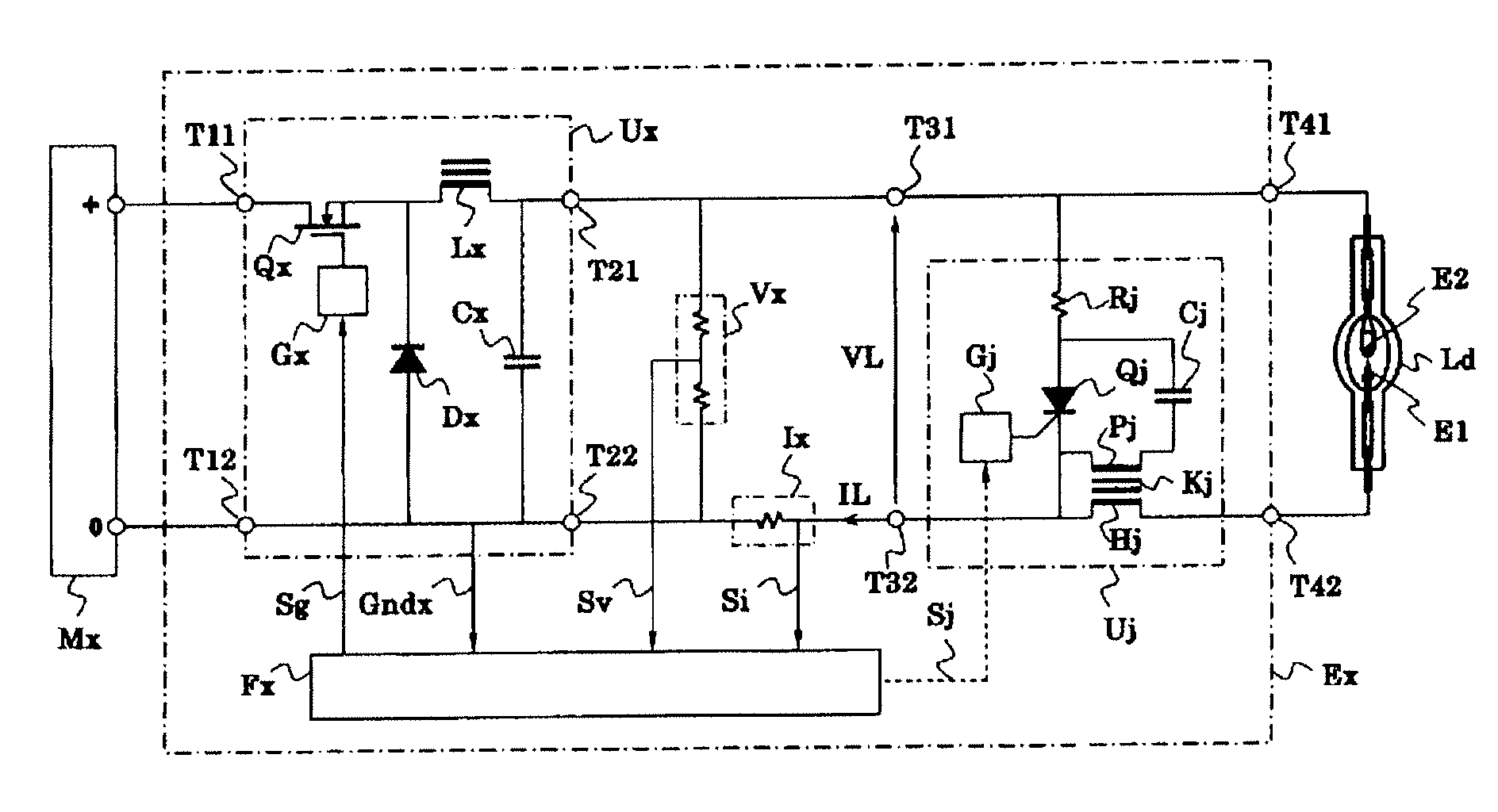
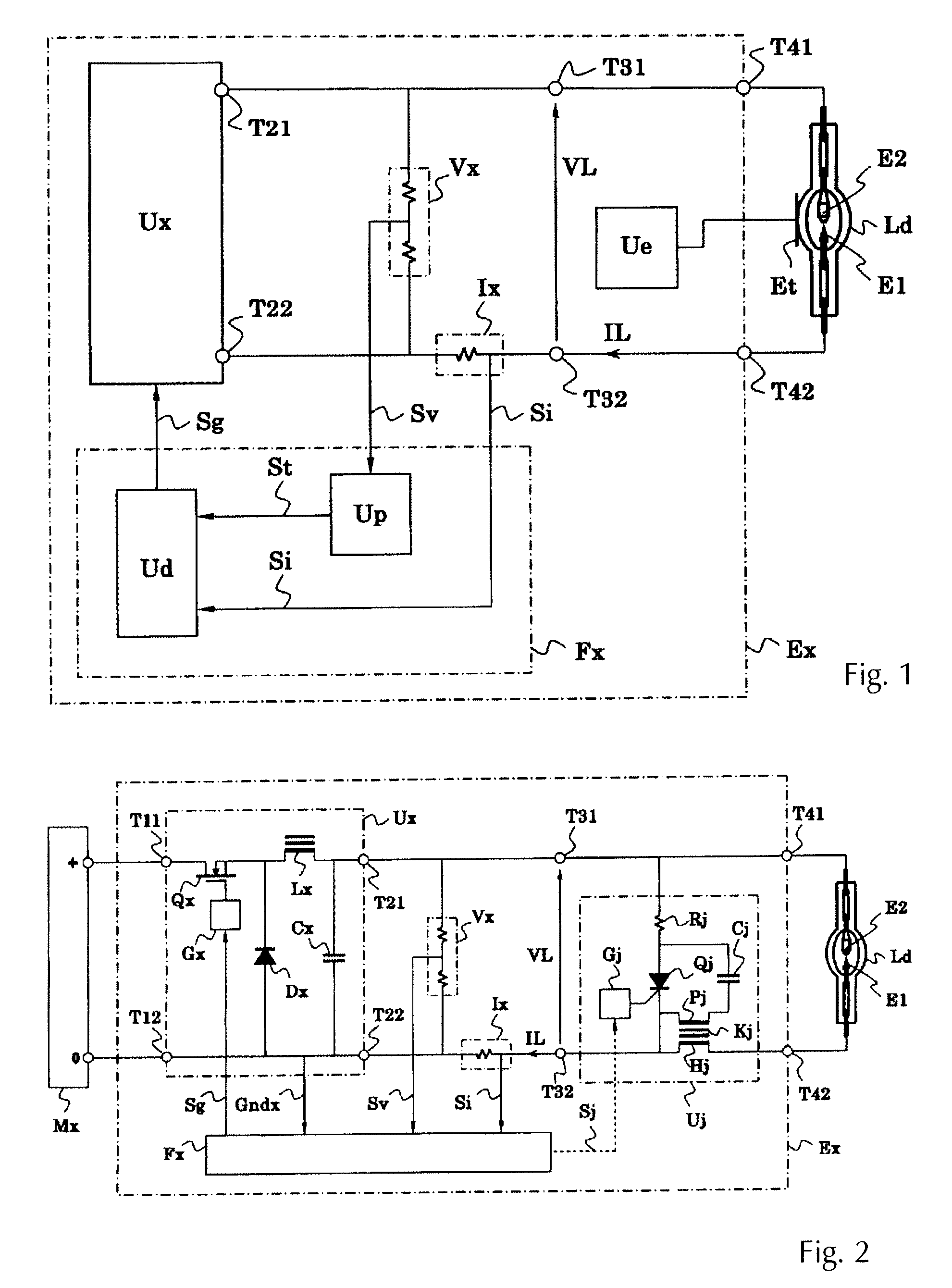
[0052]A first of embodiment of a discharge lamp ignition device in accordance with the invention is shown in FIG. 1 as having a discharge lamp Ld that is connected to a starter Ue for initiating discharge. This figure shows the case of use of the external trigger method, in which high voltage is impressed on an auxiliary electrode Et outside the sealed case of the discharge lamp Ld. The substance of this invention is, however, unrelated to the triggering method used or the location of the means for triggering ignition.

[0053]A feeder circuit Ux comprises such things as switching circuits of a step-down chopper or step-up chopper type, is connected so as to output a voltage and current that matches the condition or lighting sequence of the discharge lamp Ld and feed it to the discharge lamp Ld through the main discharge electrodes E1, E2 of the discharge lamp Ld. Now, the voltage that the feeder circuit Ux puts out as the no-load release voltage is typically from 200 to 300 V; the lam...


PUM


Abstract

To avoid the phenomenon of unsightly flickering in images projected by the projector, in high pressure discharge lamps—especially in high intensity discharge lamps, such as high pressure mercury lamps, metal halide lamps, and xenon lamps—that are used in projectors, even in the presence of the phenomenon of cyclical modulation of the lamp voltage by the returning the light spectrum when the light reflected by the dynamic color filter returns back through the optical system to the lamp, at least during steady operation of the discharge lamp (Ld), a target lamp current signal generation circuit (Up) acquires multiple lamp voltage detection signal (Sv) over a period that is at least as long as the color order cycle of the dynamic color filter (Of) and generates a target lamp current signal (St) based on the multiple lamp voltage detection signals (Sv) that were acquired.

Description

BACKGROUND OF THE INVENTION[0001]1. Field of the Invention[0002]The invention is directed to discharge lamp ignition devices for starting high pressure discharge lamps used in projectors, particularly, mercury lamps, metal halide lamps, and xenon lamps, and projectors using such discharge lamp ignition devices.[0003]2. Description of Related Art[0004]High intensity discharge lamps (HID lamps) are used in projectors for optical equipment used for displaying graphic images, such as liquid crystal projectors and DLP® projectors. One method used in these projectors for displaying color images is to split the three colors—red (R), green (G), and blue (B)—using a dichromic prism or other means, generate three separate images with a space modulation element for each color, and then recombine the light paths using a dichromic prism or other means. Another method for displaying color images is to use a spin filter which is a dynamic color filter that comprises a color wheel that passes the t...

Claims


Application Information

Patent Timeline
Patent Type & Authority Patents(United States)
IPC IPC(8): H05B37/02
CPCH05B41/2928H05B41/38Y02B20/208Y02B20/00
Inventor FUKUDA, MINORUOKAMOTO, MASASHIHORIKOSHI, MITSUO
Owner USHIO DENKI KK
Why Eureka
Try Eureka