Stereoscopic image display device having negative pressure regions within

a stereoscopic image and display device technology, applied in the field of stereoscopic image display devices, can solve the problems of thermal expansion of the gap between the liquid crystal display panel and the liquid crystal parallax barrier must be bigger, and the display quality of the stereoscopic image display device is worsened

Active Publication Date: 2008-04-29
138 EAST LCD ADVANCEMENTS LTD
View PDF18 Cites 12 Cited by
  • Summary
  • Abstract
  • Description
  • Claims
  • Application Information

AI Technical Summary

Benefits of technology

[0016]As a result of various studies, the inventor of the present invention has found that the afore-stated problems can be solved by forming the glass substrate constituting the liquid crystal display panel with non-alkali glass material and by forming the spacer member with glass material different from that of the glass substrate constituting the liquid crystal display panel in the stereoscopic image display device based on the liquid crystal parallax barrier method.
[0017]Specifically, the present invention aims to address the above-described problems, particularly, to provide a stereoscopic image display device which can be used in a large-sized stereoscopic image display device based on the liquid crystal parallax barrier method, with good display quality, and where thermal expansion of the substrate caused by heat generated by the backlight is given consideration, and the method of manufacturing the device.
[0019]According to such constitution, it is possible to regulate deformation caused by thermal expansion of the glass substrate made of non-alkali glass constituting the liquid crystal display panel as well as the spacer member due to heat generated by the backlight. Therefore, it is preferable that the spacer member comprise a glass substrate having a thermal expansion coefficient larger than that of the glass substrate constituting the liquid crystal display panel.
[0020]Further, the stereoscopic image display device according to the present invention is characterized in that the spacer member is formed of soda glass, while the glass substrate constituting the liquid crystal display panel comprises non-alkali glass. By employing a soda glass substrate, the spacer member can be made more transparent, which is not the case when other materials such as acrylic resin are used, and any increase in production cost can be controlled. Further, soda glass has certain advantages, i.e., it is not easily degraded or deformed, has a high degree of flatness, and is less likely to scratch other stacking members, and thus, a stereoscopic image display device with a suitable spacer member can be provided.
[0022]A large-sized stereoscopic image display device constituted in this manner is preferable, since the parts can be fixed more firmly as compared to the conventional fixing method of using double-sided adhesive tape. In addition, the region formed by the spacer member, the liquid crystal parallax barrier and the adhesive agent, and the region formed by the spacer member, the liquid crystal display panel and the adhesive agent are formed as negative pressure regions, so that gaps between the members can be stabilized and bend formation due to thermal expansion associated with heat generated by the backlight can be controlled.
[0025]Further, producing the stereoscopic image display device through this manufacturing method is easier compared to the conventional operation of adhering by the use of double-sided adhesive tape because only one coating of adhesive agent is required, and bubbles do not occur, yet the parts are more firmly fixed. Further, the region formed by the spacer member, the liquid crystal parallax barrier and the adhesive agent, and the region formed by the spacer member, liquid crystal panel for display and the adhesive agent are formed as negative pressure regions, so that gaps between the members can be stabilized and bend formation due to thermal expansion associated with heat generated by the backlight can be controlled.

Problems solved by technology

However, the gap between the liquid crystal display panel and the liquid crystal parallax barrier must be bigger as mentioned above as the stereoscopic image display device becomes larger.
Further, heat generated by the backlight used in the stereoscopic image display device causes thermal expansion of the liquid crystal parallax barrier, the spacer member, and the glass substrate used in the liquid crystal display panel.
Furthermore, since the distance from the backlight is different for each glass substrate, the glass substrates are consequently bent due to varying thermal expansion rates, and because the stereoscopic image display device is formed by stacking the liquid crystal parallax barrier, the spacer member, the liquid crystal display panel, the polarizing plate and the like in a plurality of steps, such bend in the substrate due to thermal expansion adversely affects the surface flatness of each such member, and necessarily worsens the display quality of the stereoscopic image display device.
Therefore, the stereoscopic image display device of the above-described Japanese Laid-Open Patent Publication No. 3-119889 does not provide a display device with sufficient display quality where the light-transmitting member such as the above-mentioned spacer member is simply arranged between the liquid crystal display panel and the liquid crystal parallax barrier.

Method used


Image

  • Stereoscopic image display device having negative pressure regions within
  • Stereoscopic image display device having negative pressure regions within
  • Stereoscopic image display device having negative pressure regions within

Examples


Embodiment Construction

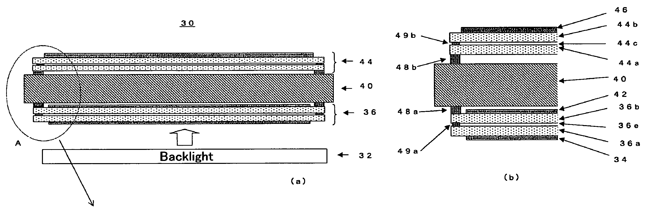
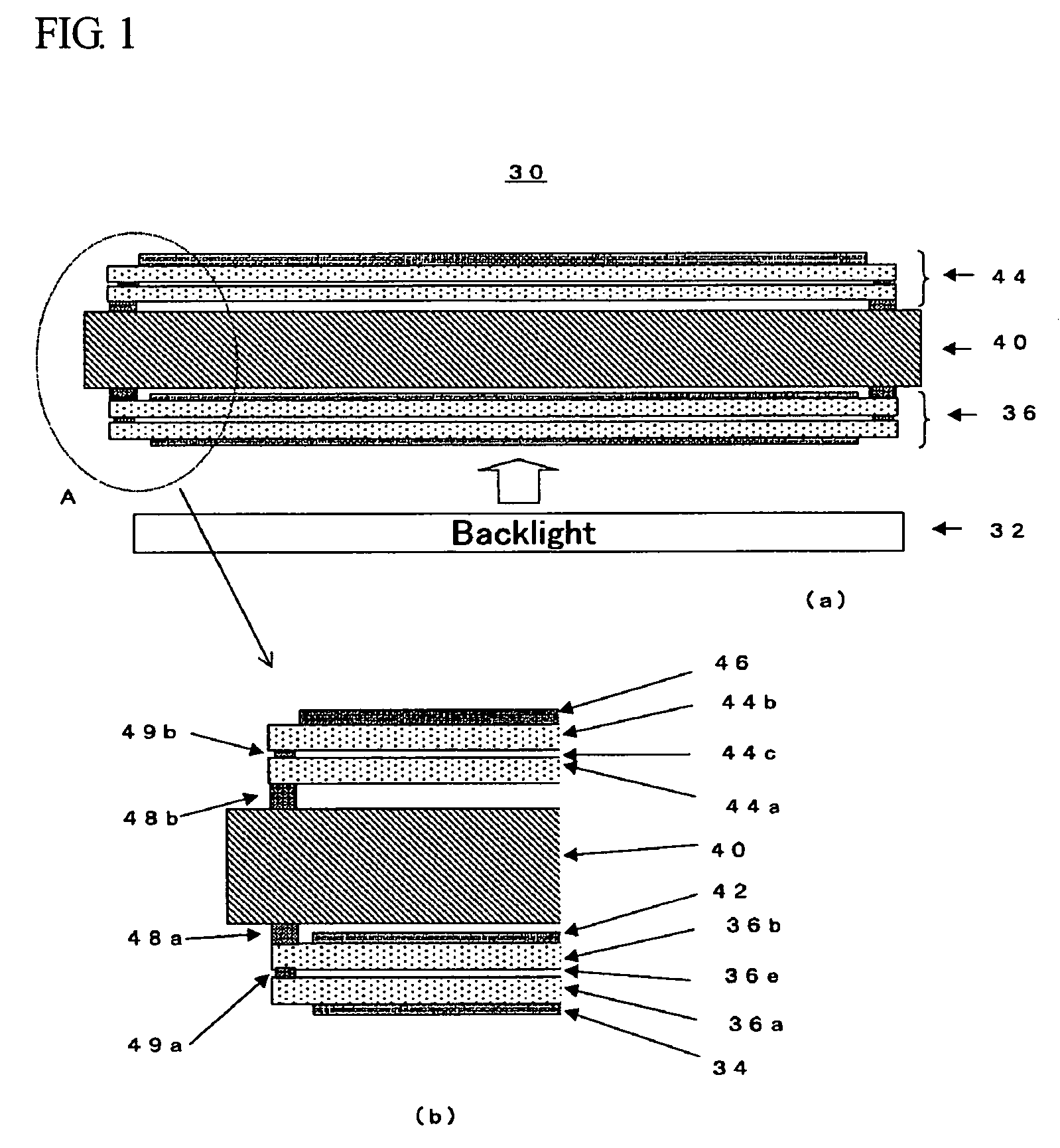
[0031]In the following, embodiments of the stereoscopic image display device according to the present invention will be described with reference to the attached drawings. FIG. 1 is the view showing the constitution of a stereoscopic image display device 30 according to the present invention, where FIG. 1(a) is a schematic cross-sectional view thereof and FIG. 1(b) is the enlarged view of the portion marked A of FIG. 1. The stereoscopic image display device 30 according to the present invention is constituted by arranging a liquid crystal display panel 36 and a liquid crystal parallax barrier 44, adhered together by an adhesive agent while sandwiching a spacer member 40 such as a glass substrate, above a backlight 32.

[0032]The liquid crystal display panel 36 is a transmissive liquid crystal panel consisting of a rear glass plate 36a located on the incident side of light, a front glass plate 36b located on the output side of light, pixel electrodes (not shown) formed on the inner side...


PUM

PropertyMeasurementUnit
pressureaaaaaaaaaa
thermal expansionaaaaaaaaaa
shapeaaaaaaaaaa

Abstract

A stereoscopic image display device 30 comprising a backlight 32, a liquid crystal display panel 36, a liquid crystal parallax barrier 44, and a spacer member 40 arranged between the liquid crystal display panel 36 and the liquid crystal parallax barrier 44, in which the spacer member 40 is made of a glass material different from that of the glass substrates 36a, 36b constituting the liquid crystal display panel 36, and the spacer member 40 is a glass substrate having a thermal expansion coefficient larger than that of the glass substrates 36a, 36b constituting the liquid crystal display panel 36. More specifically, it is preferable that the spacer member 40 consist of a soda glass substrate and that the liquid crystal display panel 36 for display be formed of non-alkali glass. With this constitution, it is possible to provide a stereoscopic image display device, which can be used as a large-sized stereoscopic image display device by means of the liquid crystal parallax barrier method, with good display quality and where due consideration has been given to the thermal expansion of the substrate caused by heat generated by the backlight, and the manufacturing method therefor.

Description

[0001]This application is a national stage entry under 35 U.S.C. §371 of PCT / JP04 / 04003, filed Mar. 24, 2004, (designating the U.S.; and which published in Japanese in WO 2004 / 086127 on Oct. 7, 2004), which claims the benefit of Japanese Patent Application Nos. 2003-082897 and 2003-082898, both filed Mar. 25, 2003, incorporated herein by reference.TECHNICAL FIELD[0002]The present invention relates to a stereoscopic image (picture) display device based on a liquid crystal parallax barrier system, which is capable of stereoscopic image display without using special glass and more specifically, to a stereoscopic image display device where consideration is given to the thermal expansion of the substrate caused by heat generated by a backlight, and the method of manufacturing the device.BACKGROUND ART[0003]The known conventional methods of displaying stereoscopic images without using special glass are the lenticular method, the parallax barrier method, and a method in which a light sourc...

Claims


Application Information

Patent Timeline
Patent Type & Authority Patents(United States)
IPC IPC(8): G02F1/1335G02B30/31G02F1/1347
CPCG02B27/2214G02F1/1347G02B30/31G02F1/1335G02B30/27
Inventor TANAKA, SHINICHIROARAMATSU, YOSHIAKI
Owner 138 EAST LCD ADVANCEMENTS LTD
Why Eureka
Try Eureka