Military UHF and commercial Geo-mobile system combination for radio signal relay

a geo-mobile system and military technology, applied in multiplex communication, frequency-division multiplex, wireless commuication services, etc., can solve the problem of large equipment investment and retard the transition to state-of-the-art equipmen

Inactive Publication Date: 2008-04-29
HUGHES ELECTRONICS
View PDF46 Cites 104 Cited by
  • Summary
  • Abstract
  • Description
  • Claims
  • Application Information

AI Technical Summary

Benefits of technology

[0011]The present invention relates to relaying radio signals in multi-mode communication systems. The present invention overcomes expensive system transitions to exclusive communication techniques by employing a system and device for communicating two or more distinct modes (i.e., carrier frequency and protocol) of signals wherein transmitting d...

Problems solved by technology

However, a practical problem with changing over from older to newer technologies is...

Method used


Image

  • Military UHF and commercial Geo-mobile system combination for radio signal relay
  • Military UHF and commercial Geo-mobile system combination for radio signal relay
  • Military UHF and commercial Geo-mobile system combination for radio signal relay

Examples


Embodiment Construction

[0024]Although the following description focuses on systems and devices for relaying dual mode radio signals using a satellite, persons of ordinary skill in the art will readily appreciate the techniques of the present invention are in no way limited to dual mode radio signals or satellites. On the contrary, any system with multiple modes of communication and / or the need to relay signals may benefit from the techniques described and illustrated herein. For example, wired or wireless communication systems transmitting information to and from a plurality of devices could employ the techniques provided herein without departing from the scope of the invention.

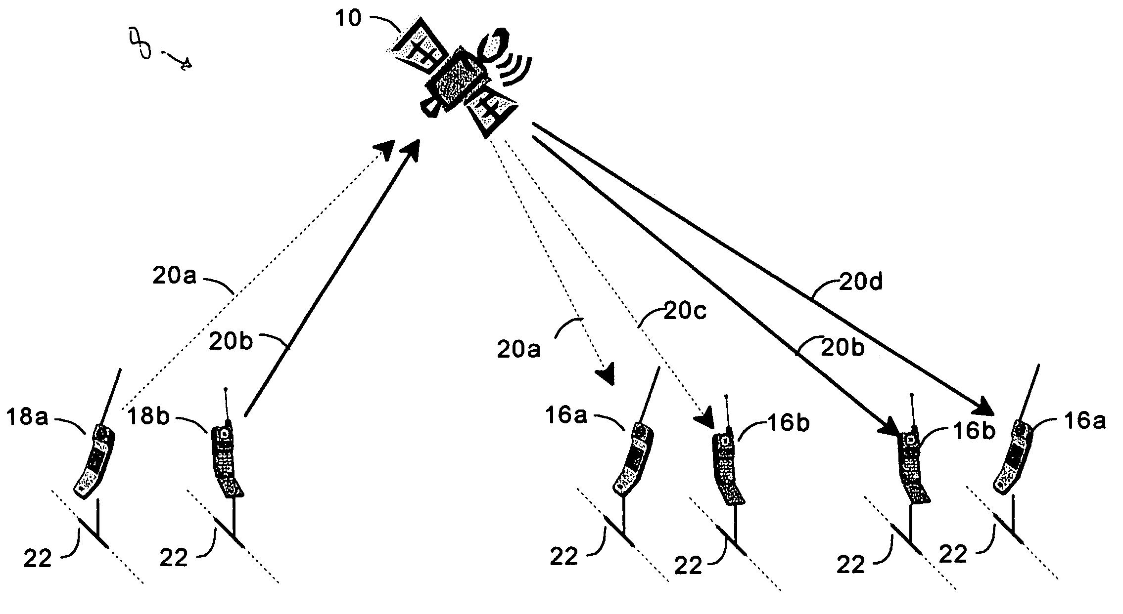
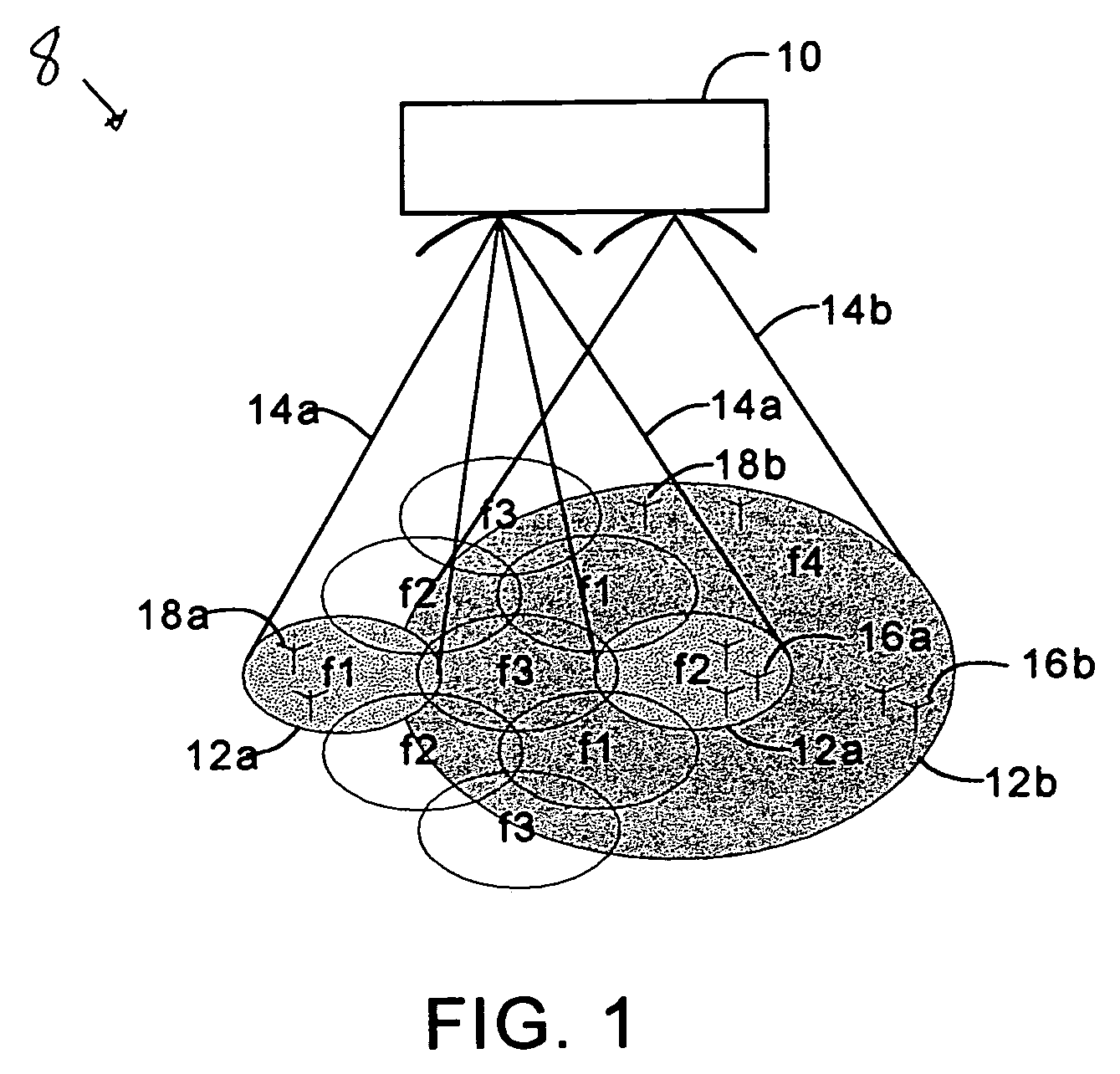
[0025]A diagram of a communication system 8 for communicating radio signals, capable of utilizing the teachings of the present invention, is shown in FIG. 1. A radio signal relay device 10, such as a beam forming satellite, is used to cover several relatively small geographical regions 12a. Beams 14a with sufficient angular separat...


PUM


Abstract

A radio signal relay device such as satellite is used to cover several relatively small geographical regions with relatively narrow beams as well as a relatively large geographical region with a single beam. This relatively wide beam permits legacy equipment to be used. A transmitting device in a beam transmits a signal to the relay device, which in turn retransmits the signal to a receiving device. The transmitting devices, relay device, and receiving devices synchronize communication by using a particular mode of communication which includes a band of carrier frequencies and a protocol. In addition to communicating like mode signals from a transmitter to a receiver, the relay device may be used in a dual mode communication system to translate signals from the one mode to another. A translator may direct a transmitter to modulate a signal on a different carrier frequency, convert one protocol into another protocol, or both.

Description

CROSS REFERENCE TO RELATED APPLICATIONS[0001]This application is related to the following United States patent applications:[0002]Ser. No. 09 / 552,297, filed Apr. 19, 2000, now issued as U.S. Pat. No. 6,711,398;[0003]Ser. No. 10 / 418,492, which is a divisional application of Ser. No. 09 / 552,297, filed on Apr. 18, 2003 and now issued as U.S. Pat. No. 6,985,716;[0004]Ser. No. 11 / 254,322, which is a continuation of Ser. No. 10 / 418,492, filed Oct. 20, 2005 and now issued as U.S. Pat. No. 7,120,434;[0005]Ser. No. 11 / 517,074, which is a continuation of Ser. No. 11 / 254,322, filed Sep. 7, 2006; and[0006]Ser. No. 09 / 522,296, filed Apr. 19, 2000, now abandoned.TECHNICAL FIELD OF THE INVENTION[0007]The present invention relates in general to radio signal relay systems and more specifically to devices having dual mode communication.BACKGROUND OF THE INVENTION[0008]Radio communication systems rely on modulating carrier frequencies in a finite portion of the electromagnetic spectrum to wirelessly t...

Claims


Application Information

Patent Timeline
IPC IPC(8): H04B7/185
CPCH04B7/18563H04B7/2041
Inventor ARCHER, STEPHEN F.JOHNSON, RICHARD H.
Owner HUGHES ELECTRONICS
Why Eureka
Try Eureka