
Access point operating with a smart antenna in a WLAN and associated methods

a smart antenna and access point technology, applied in the field of wireless communication, can solve the problems of reducing the range in which client stations can access the network via the access point, affecting the throughput of the network, and low omni-directional antenna, so as to increase the range between an access point and client stations and increase the network throughput

Inactive Publication Date: 2008-04-29
INTERDIGITAL TECH CORP
View PDF9 Cites 28 Cited by
  • Summary
  • Abstract
  • Description
  • Claims
  • Application Information

AI Technical Summary

Benefits of technology

The present invention provides a method for an access point to increase the range between it and client stations and to increase network throughput in an 802.11 wireless communication network. This is achieved by scanning the access point's antenna beams and measuring the signals received from the client stations using the selected beams. The access point uses an antenna steering algorithm to select the best antenna beam for each client station. The method also includes rules for exchanging data with the client station and may transmit acknowledgements using the selected antenna beam. The technical effects of the invention include increased range and throughput, improved network performance, and better user experience.

Problems solved by technology

As a result, the antenna gain of an omni-directional antenna is generally low, resulting in a reduced range in which client stations can access the network via the access point.
Moreover, the throughput of the network is adversely affected by low gain omni-directional antennas.

Method used


Image

  • Access point operating with a smart antenna in a WLAN and associated methods
  • Access point operating with a smart antenna in a WLAN and associated methods
  • Access point operating with a smart antenna in a WLAN and associated methods

Examples


Embodiment Construction

[0033]The present invention will now be described more fully hereinafter with reference to the accompanying drawings, in which preferred embodiments of the invention are shown. This invention may, however, be embodied in many different forms and should not be construed as limited to the embodiments set forth herein. Rather, these embodiments are provided so that this disclosure will be thorough and complete, and will fully convey the scope of the invention to those skilled in the art. Like numbers refer to like elements throughout.

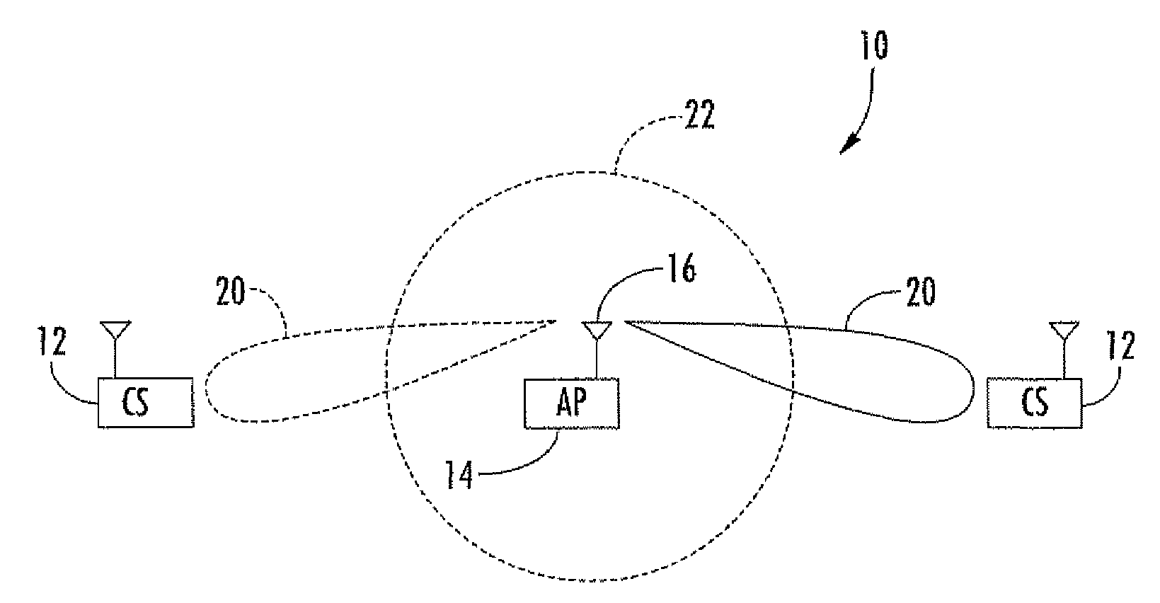
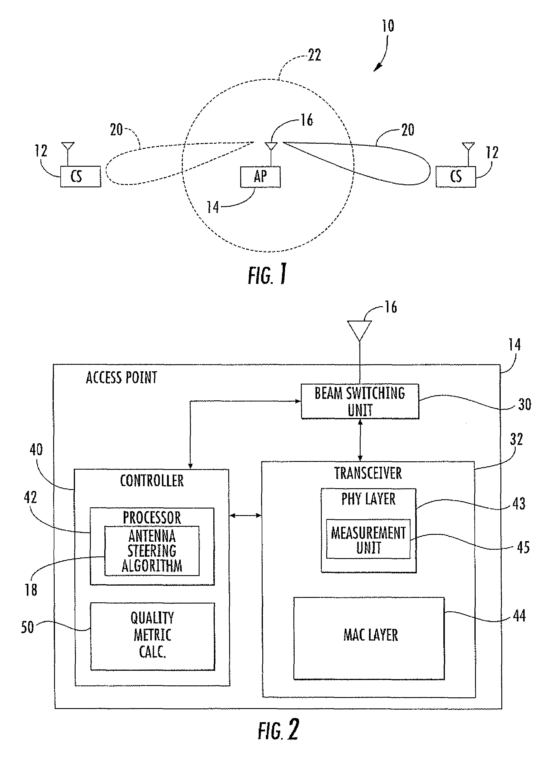
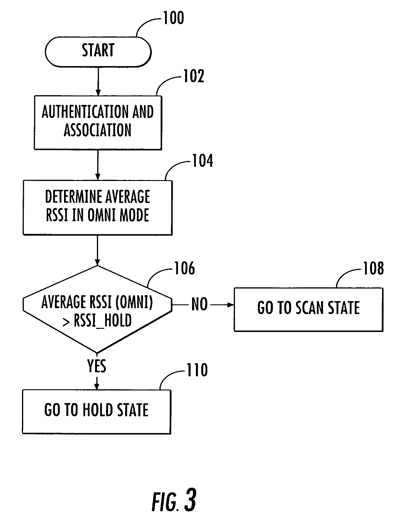
[0034]Referring initially to FIGS. 1 and 2, an 802.11 wireless local area network (WLAN) 10 includes client stations 12, and an access point 14 operating with a subscriber based smart antenna 16 in accordance with the present invention. The smart antenna 16, which will also be referred to as a switched beam antenna, generates a plurality of antenna beams in response to an antenna steering algorithm 18. The antenna beams generated by the smart antenna 16 in...


PUM


Abstract

An access point operates in an 802.11 wireless communication network communicating with a client station, and includes a smart antenna for generating directional antenna beams and an omni-directional antenna beam. An antenna steering algorithm scans the directional antenna beams and the omni-directional antenna beam for receiving signals from the client station. The signals received via each scanned antenna beam are measured, and one of the antenna beams is selected based upon the measuring for communicating with the client station. The selected antenna beam is preferably a directional antenna beam. Once the directional antenna beam has been selected, there are several usage rules for exchanging data with the client station. The usage rules are directed to an active state of the access point, which includes a data transmission mode and a data reception mode.

Description

RELATED APPLICATION[0001]This application claims the benefit of U.S. Provisional Application Ser. Nos. 60 / 577,334 filed Jun. 4, 2004 and 60 / 587,962 filed Jul. 14, 2004, the entire contents of which are incorporated herein by reference.FIELD OF THE INVENTION[0002]The present invention relates to the field of wireless communications, and more particularly, to an antenna steering algorithm for an access point operating with a smart antenna in an 802.11 wireless local area network (WLAN).BACKGROUND OF THE INVENTION[0003]A wireless local area network (WLAN) uses radio waves rather than wires to communicate between nodes. WLANs are flexible communication systems seen as an alternative to, or an extension of wired LANs. An access point is a hardware device that acts as a communication hub for users of a wireless device to connect to the LAN. Access points are important for extending the physical range of service in which a wireless user has access to the LAN. Access points also affect the ...

Claims


Application Information

Patent Timeline
Patent Type & Authority Patents(United States)
IPC IPC(8): H04B7/14H04W16/24
CPCH04W16/24H04B7/088H04B7/0695
Inventor IACONO, ANA LUCIACHANDRA, ARTYSTEINBACH, DANIEL P.CHA, INHYOKOTTO, JAMES C.JOHNSON, KEVIN P.GUTOWSKI, STANLEYLIU, KAICUFFARO, ANGELOSTERN-BERKOWITZ, JANET
Owner INTERDIGITAL TECH CORP
Learn More