Minimum force output control method for counter-mass with cable

a counter-mass and cable technology, applied in the direction of force/torque/work measurement apparatus, instruments, digital computer details, etc., can solve the problems of deteriorating exposure performance, reducing the control accuracy of the position of the wafer table in the z-axis direction, and so as to reduce or eliminate the vibration of the lens body

Active Publication Date: 2008-04-29
NIKON CORP
View PDF6 Cites 2 Cited by
  • Summary
  • Abstract
  • Description
  • Claims
  • Application Information

AI Technical Summary

Benefits of technology

[0008]Embodiments of the present invention are directed to taking into account the cable force in the counter-mass trajectory computation to reduce or eliminate vibration of the lens body caused by the cable force disturbance and corrective force exerted by the trim motors. To do so, a cable force feedforward approach is used to provide cable force identification and modeling, feedforward trajectory generation, and weighting function for optimization.

Problems solved by technology

In such cases, when vibration occurs in a wafer stage supporting member that exceeds a predetermined amount, the vibration cannot be attenuated sufficiently, which causes the control accuracy of the position of the wafer table in the Z-axis direction to decrease.
The reaction force will transmit to the lens body and cause vibration of the lens body.
The vibration will deteriorate the exposure performance.

Method used


Image

  • Minimum force output control method for counter-mass with cable
  • Minimum force output control method for counter-mass with cable
  • Minimum force output control method for counter-mass with cable

Examples


Embodiment Construction

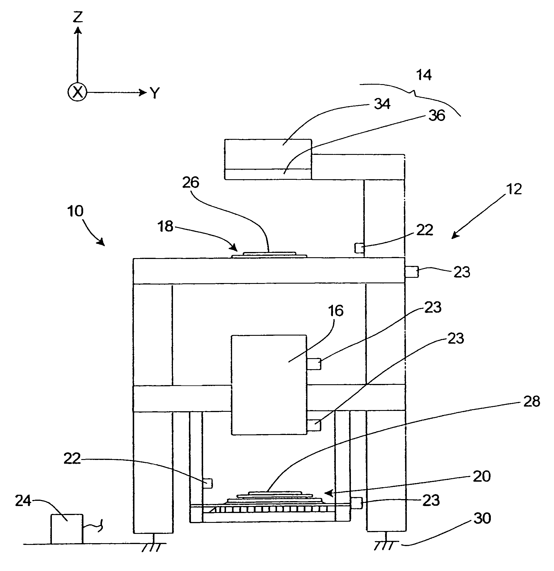
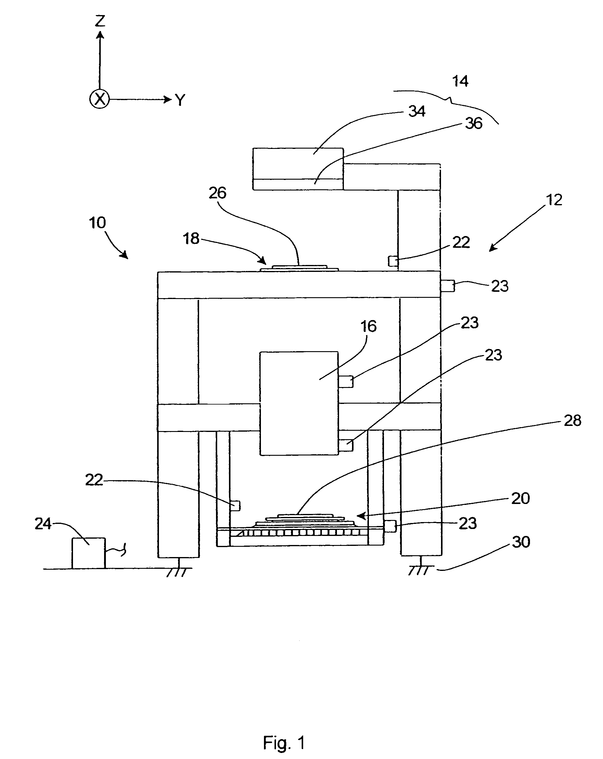
[0038]FIG. 1 is a schematic illustration of a precision assembly, namely, an exposure apparatus 10. The exposure apparatus 10 includes an apparatus frame 12, an illumination system 14 (irradiation apparatus), an assembly 16 such as an optical assembly, a reticle stage assembly 18, a wafer stage assembly 20, a measurement system 22, one or more sensor 23, and a control system 24 having features of the present invention. The control system 24 may be a computer having a processor and a memory storing codes and data to be processed and executed by the processor. The specific design of the components of the exposure apparatus 10 may be varied to suit the design requirements of the particular application.

[0039]As provided herein, the control system 24 utilizes a position compensation system or module that improves the accuracy in the control and relative positioning of at least one of the stage assemblies 18, 20. An orientation system used herein includes an X axis, a Y axis which is orth...


PUM


Abstract

Embodiments of the invention relate to a cable force feedforward approach that takes into account the cable force in the counter-mass trajectory computation to reduce or eliminate vibration of the lens body caused by the cable force disturbance and corrective force exerted by the trim motors. In one embodiment, a method provides cable force feedforward control for a counter-mass of a stage with a cable connected to the counter-mass and using the cable force feedforward control to control one or more trim motors to produce a trim motor output force to be applied to the counter-mass, the counter-mass moving in response to a reaction force from movement of the stage. The method comprises measuring a counter-mass position y of the counter-mass in response to forces applied to the counter-mass; measuring a cable force ƒ exerted on the counter-mass by the cable which is connected to the counter-mass; generating a cable force function {circumflex over (ƒ)}(y, {dot over (y)}) of the measured cable force ƒ versus the counter-mass position y; and computing the trim motor output force u asu≅-f+w·f^⁡(y,y.),where w is a weighting function having a value from 0 to 1 and is selected for optimization.

Description

CROSS-REFERENCES TO RELATED APPLICATIONS[0001]Not ApplicableBACKGROUND OF THE INVENTION[0002]The present invention relates generally to a control system and method for controlling the trajectory and alignment of one or more stages in a semiconductor wafer exposure system and, more particularly, to reducing the output forces of stage counter-mass trim motors in the existence of cable force disturbances or the like.[0003]In a conventional photolithographic process for manufacturing devices such as semiconductors and liquid crystal display devices, projection exposure apparatus of a sequential moving type such as a reduction projection exposure apparatus based on a step-and-repeat method (a so-called stepper) that reduces and transfers a pattern formed on a mask or a reticle (hereinafter generally referred to as a “reticle”) onto a substrate such as a wafer or a glass plate (hereinafter generally referred to as a “wafer”) coated with a resist or the like via a projection optical system...

Claims


Application Information

Patent Timeline
Patent Type & Authority Patents(United States)
IPC IPC(8): G06F15/00
CPCG03F7/70725G03F7/70766
Inventor HSIN, YI-PINGSZOBOSZLAY, GABOR D.HIRANO, KAZUHIROMASAKI, KAZUOSMITH, CHRISTOPHER B.KAWAGUCHI, RYOICHIYUAN, BAUSAN
Owner NIKON CORP
Why Eureka
Try Eureka