Low leakage finger seal

a finger seal and low leakage technology, applied in the field of finger seals, can solve the problems of limited success of staggered slots, complicated manufacture and assembly, and difficulty in reducing leakage through gaps

Active Publication Date: 2008-05-06
RTX CORP
View PDF13 Cites 58 Cited by
  • Summary
  • Abstract
  • Description
  • Claims
  • Application Information

AI Technical Summary

Benefits of technology

[0006]This invention is an exhaust duct assembly seal that includes a metal mesh member disposed between slotted inner and outer plates for substantially reducing leakage through gaps created by the slotted inner and outer plates.
[0007]The seal includes a metal mesh member sandwiched between an outer plate and an inner plate. The seal is biased against a seal land. The seal includes a plurality of flexible members defined by a plurality of slots in both the inner and outer plates. The flexible members provide for expansion and contraction along with creating flexibility in the region of contact between the seal land and the seal. The metal mesh member substantially eliminates gaps and leak paths created through the slots.
[0008]The metal mesh member is composed of a plurality of interwoven wire strands. The mesh member is impregnated with a high temperature elastomeric sealant. The impregnation of high temperature elastomeric sealant over the metal mesh member improves sealing while maintaining the desired flexibility of the seal.
[0009]The seal of this invention includes a metal mesh member impregnated with a high temperature elastomeric sealant providing an improved seal while maintaining the desired flexibility between a fixed portion and a movable portion of an exhaust duct assembly.

Problems solved by technology

Disadvantageously, the slots create leak paths through which exhaust gases can intrude.
Such staggered slots are of limited success as leak paths may still form.
Disadvantageously, cloth degrades and frays over time.
Further the use of cloth complicates manufacture and assembly.

Method used


Image

  • Low leakage finger seal
  • Low leakage finger seal
  • Low leakage finger seal

Examples


Embodiment Construction

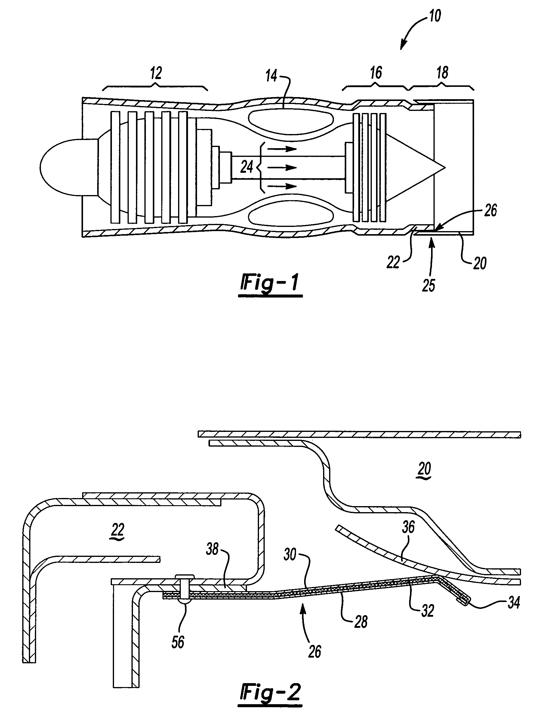
[0017]Referring to FIG. 1, a gas turbine engine assembly 10 includes a compressor 12 for compressing incoming air. Compressed air is mixed with fuel in a combustor 14 and ignited to generate an axial flow of hot exhaust gases 24. The hot exhaust gases drive a turbine 16 that in turn drives the compressor 12. An exhaust duct assembly 18 directs the out going exhaust gases 24. The exhaust duct assembly 18 includes a fixed part 22 and a movable part 20 for selectively directing exhaust gases 24. The interface 25 between the fixed part 22 and movable part 20 includes a seal 26 for substantially preventing leakage of exhaust gases radially from the exhaust duct assembly 18.

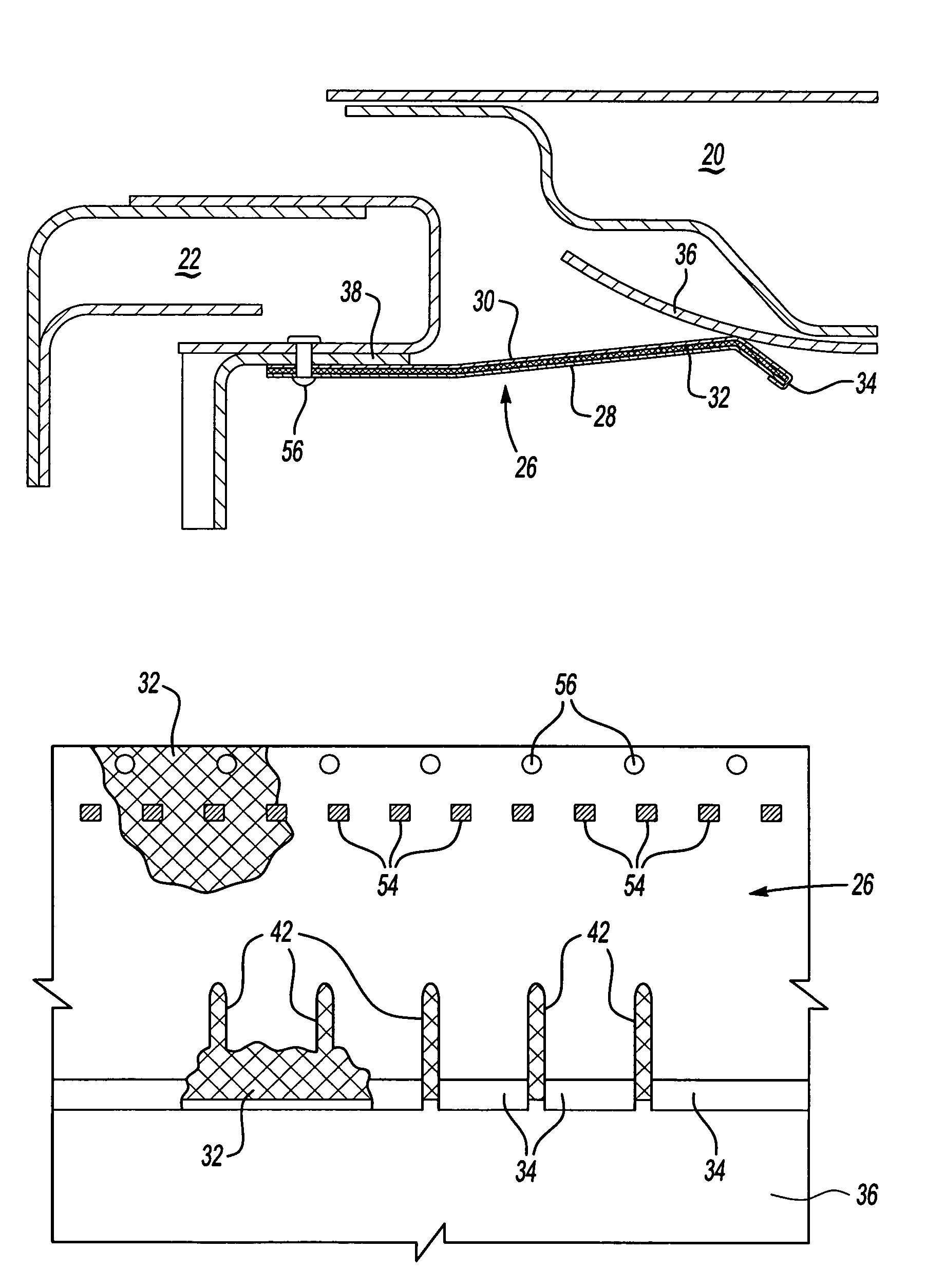
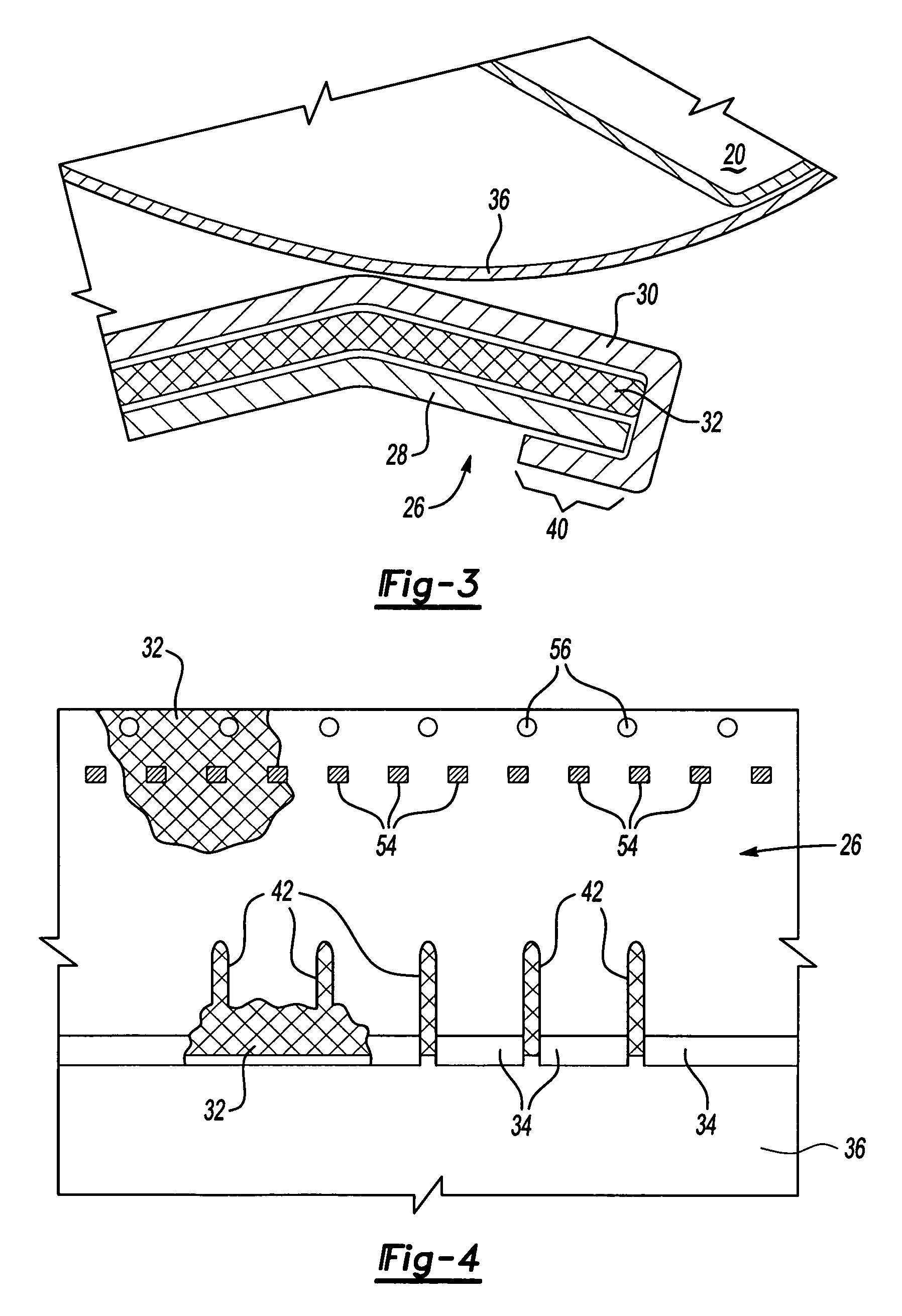
[0018]Referring to FIG. 2, the seal 26 is biased into sealing contact with a seal land 36. The seal 26 includes an outer plate 28 that is exposed to the gas stream 24 and an inner plate 30 that is in contact with the seal land 36. A metal mesh member 32 is sandwiched between the outer plate 28 and the inner plate 30. T...


PUM


Abstract

A seal for an exhaust duct includes a metal mesh member sandwiched between an outer plate and an inner plate. The seal includes a plurality of flexible members defined by a plurality of slots in both the inner and outer plates. The flexible members provide for expansion and contraction along with creating flexibility in the region of contact between the seal land and the seal. The metal mesh member substantially eliminates gaps and leak paths created through the slots. The metal mesh member is composed of a plurality of interwoven wire strands impregnated with a high temperature elastomeric sealant. The impregnation of high temperature elastomeric sealant over the metal mesh member improves sealing while maintaining the desired flexibility of the seal.

Description

[0001]The U.S. Government may have certain rights in this invention in accordance with Contract Number N00019-02-C-3003 awarded by the United States Navy.BACKGROUND OF THE INVENTION[0002]This invention generally relates to a seal between a fixed member and a movable member. More particularly, this invention relates to a finger seal for an exhaust duct assembly.[0003]A gas turbine engine typically includes an exhaust duct for directing exhaust gases. Many exhaust duct assemblies include a movable portion for selectively directing the exhaust gases. Such exhaust duct assemblies includes a fixed portion and a movable portion. A seal is required between the fixed and movable portions to prevent intrusion of exhaust gases through the exhaust nozzle assembly at the interface between the fixed and movable portions.[0004]The seal is typically provided with a plurality of fingers that are formed by a corresponding plurality of slots. The slots and finger configuration provide for flexing and...

Claims


Application Information

Patent Timeline
Patent Type & Authority Patents(United States)
IPC IPC(8): F01D11/00
CPCF01D11/003F01D25/30F02C7/28F02K1/002F16J15/0812F16J15/126
Inventor FARAH, JORGENEWELL, LAURAKEHRET, DEBORA
Owner RTX CORP
Why Eureka
Try Eureka