Cable connector for selective wiring

a cable connector and selective wiring technology, applied in the direction of electrical equipment, substation/switching arrangement details, coupling device connections, etc., can solve the problems of non-economic cost, cost and work load

Inactive Publication Date: 2008-05-06
AGENCY FOR DEFENSE DEV
View PDF4 Cites 8 Cited by
  • Summary
  • Abstract
  • Description
  • Claims
  • Application Information

AI Technical Summary

Problems solved by technology

Furthermore, in the case where the length of the cable is long because the distance between the measurement equipment and the sensor is far, if a system for mobile measurement it is non-economical in terms of cost. a problem arises because the size of the cable and the connector is big.
Accordingly, this method is disadvantageous in that it is non-economical in terms of the cost and work load and requires many cable connectors that must be managed.

Method used


Image

  • Cable connector for selective wiring
  • Cable connector for selective wiring
  • Cable connector for selective wiring

Examples


Embodiment Construction

[0017]The present invention will now be described in detail in connection with preferred embodiments with reference to the accompanying drawings.

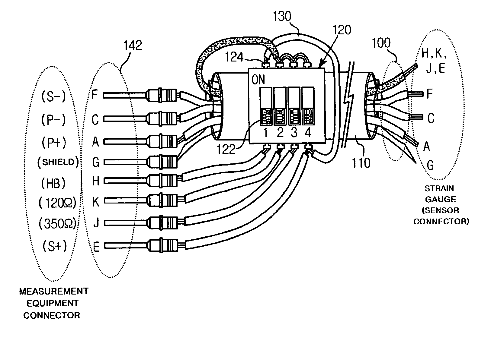
[0018]FIG. 1 is a perspective view of a cable connector for selective wiring according to an embodiment of the present invention.

[0019]The cable connector according to an embodiment of the present invention may be applied to a strain measurement system, as shown in FIG. 1. The cable connector may be constructed to connect a strain gauge (or a sensor using the strain gauge such as a pressure transducer or a load cell) and a measurement equipment (a signal amplifier). The cable connector includes a cable 110 containing plural pieces of electric wires 100, and a DIP switch 120 arranged on the cable 110.

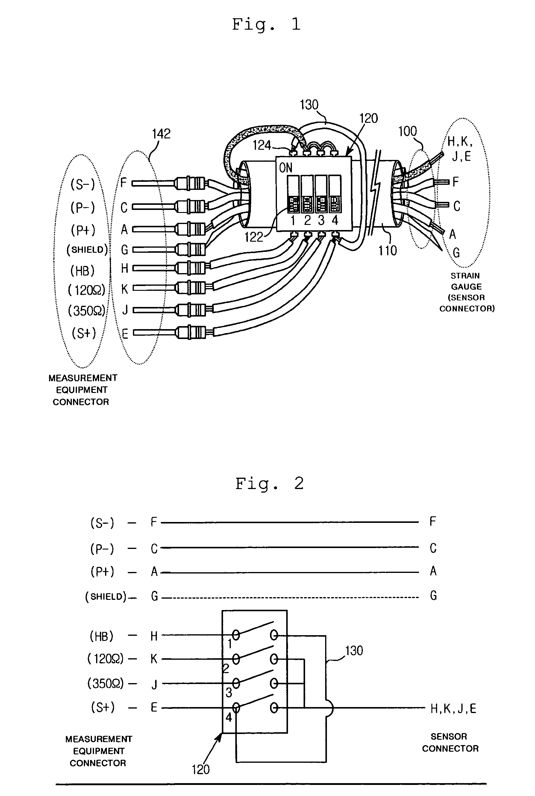
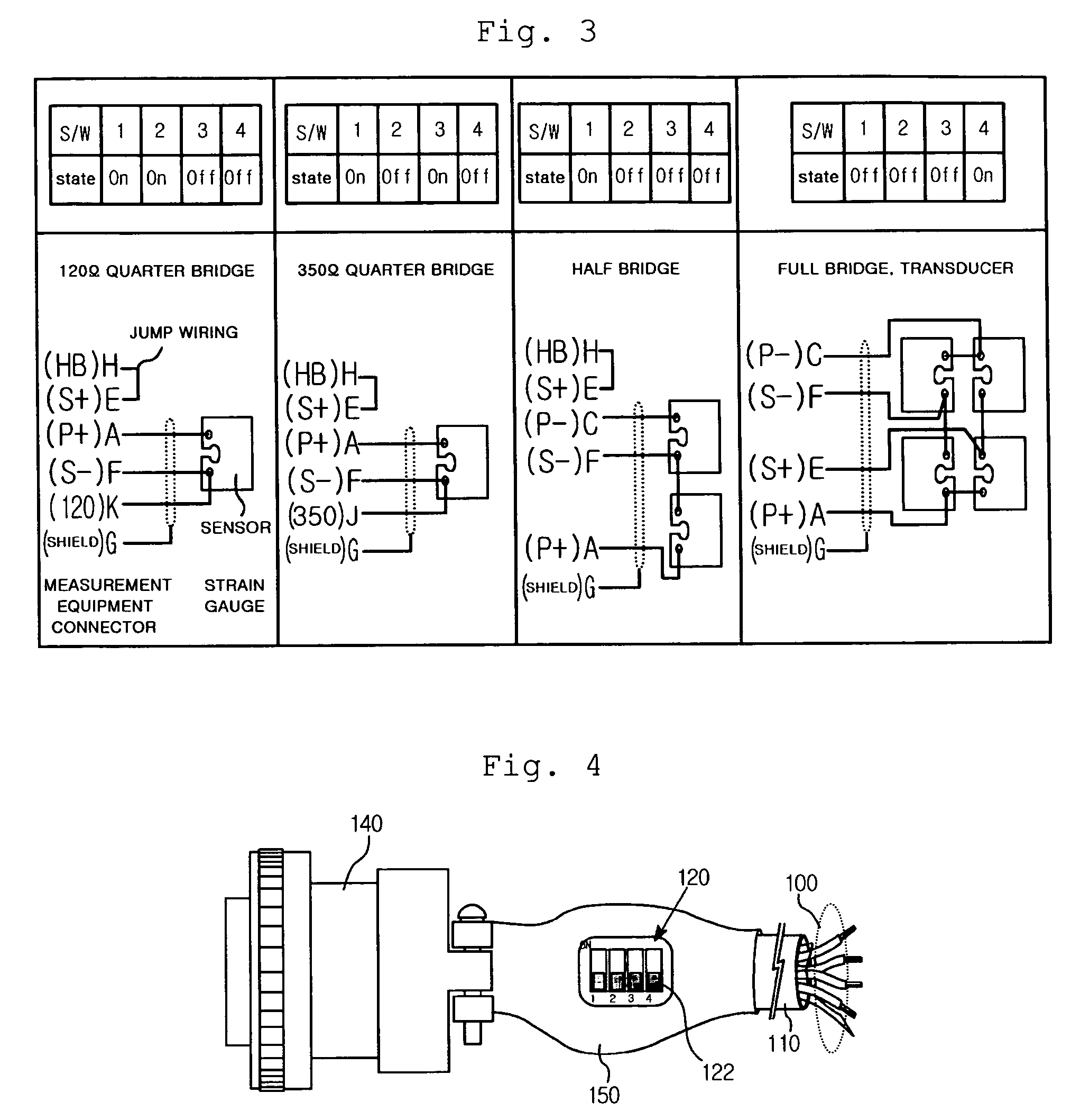
[0020]The DIP switch 120 shown in FIG. 1 is a commercial slide type 4-pole DIP switch. The DIP switch is constructed to form wiring in an “on” state and disconnects the wiring in an “off” state.

[0021]In FIGS. 1 to 3, the alphabets H, E, A, F, K,...


PUM


Abstract

The present invention relates to a strain gauge interfacing cable connector for selective wiring. A DIP switch 120 is disposed on a cable 110 of the cable connector, and electric wires and the DIP switch 120 are wired in a given arrangement. Accordingly, a variety of wiring systems can be implemented using a minimal number of electric wires through mechanical manipulation of the DIP switch 120 and minimal artificial wiring modification. The cable connector includes a cable 110 for containing a plurality of electric wires; a commercial connector 140; and a DIP switch 120 disposed on the cable 110 of a location adjacent to the commercial connector 140 of the cable, whereby a predetermined internal wiring can be switched by selectively manipulating switch control units 122 of the DIP switch 120 depending on a use.

Description

BACKGROUND OF THE INVENTION[0001]1. Field of the Invention[0002]The present invention relates to a cable connector for selective wiring. More particularly, the present invention relates to a cable connector for selective wiring, wherein a DIP (Dual In-line Package) switch is disposed on a cable, and electric wires and the DIP switch are wired in a given arrangement, whereby a variety of wiring systems can be implemented through only mechanical manipulation of the DIP switch, or the manipulation of the DIP switch and minimal artificial wiring modification.[0003]2. Background of the Related Art[0004]For example, in strain measurement employing the strain gauge, the wiring method of the sensor (the strain gauge) and the measurement equipment (the signal amplifier) may include four kinds of wiring methods such as a quarter bridge wiring method using one strain gauge of 120Ω, a quarter bridge wiring method using one strain gauge of 350Ω, a half bridge wiring method using two strain gauge...

Claims


Application Information

Patent Timeline
Patent Type & Authority Patents(United States)
IPC IPC(8): H01R29/00
CPCH01R29/00H01R13/70
Inventor LEE, HWAN-GYUKIM, SHIN-HOE
Owner AGENCY FOR DEFENSE DEV
Why Eureka
Try Eureka