Coil component

a technology of coils and components, applied in the direction of transformers/inductance details, inductances, basic electric elements, etc., can solve the problems of insufficient number of turns for achieving high inductance, etc., to achieve low stray capacitance and high inductance

Active Publication Date: 2008-05-06
MURATA MFG CO LTD
View PDF14 Cites 14 Cited by
  • Summary
  • Abstract
  • Description
  • Claims
  • Application Information

AI Technical Summary

Benefits of technology

[0017]To overcome the problems described above, preferred embodiments of the present invention provide a coil component in which both low stray capacitance and high inductance are achieved.

Problems solved by technology

However, with the coil component 100 having the multi-turn spiral pattern 101 within a single layer, a sufficient number of turns for achieving high inductance cannot be obtained due to space limitations.
However, although the stray capacitance can be reduced in the coil component 300 shown in FIG. 14, a sufficient number of turns for achieving high inductance cannot be obtained.
Therefore, due to space limitations, a sufficient number of annular patterns 311 to 316 cannot be obtained, which prevents the pattern group 301 from having a sufficient number of turns.
Consequently, it is difficult to achieve high inductance of the coil component 300.

Method used


Image

  • Coil component
  • Coil component
  • Coil component

Examples


first preferred embodiment

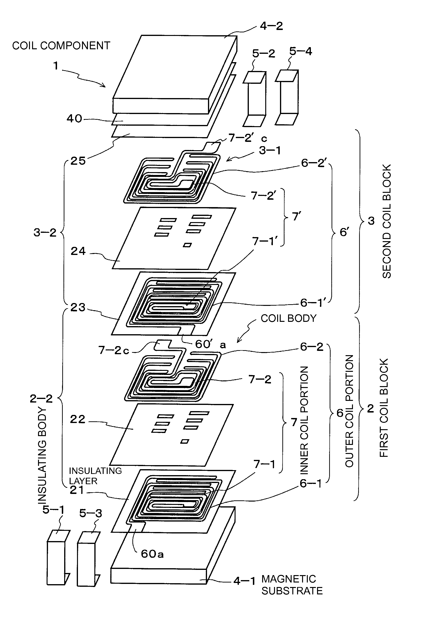
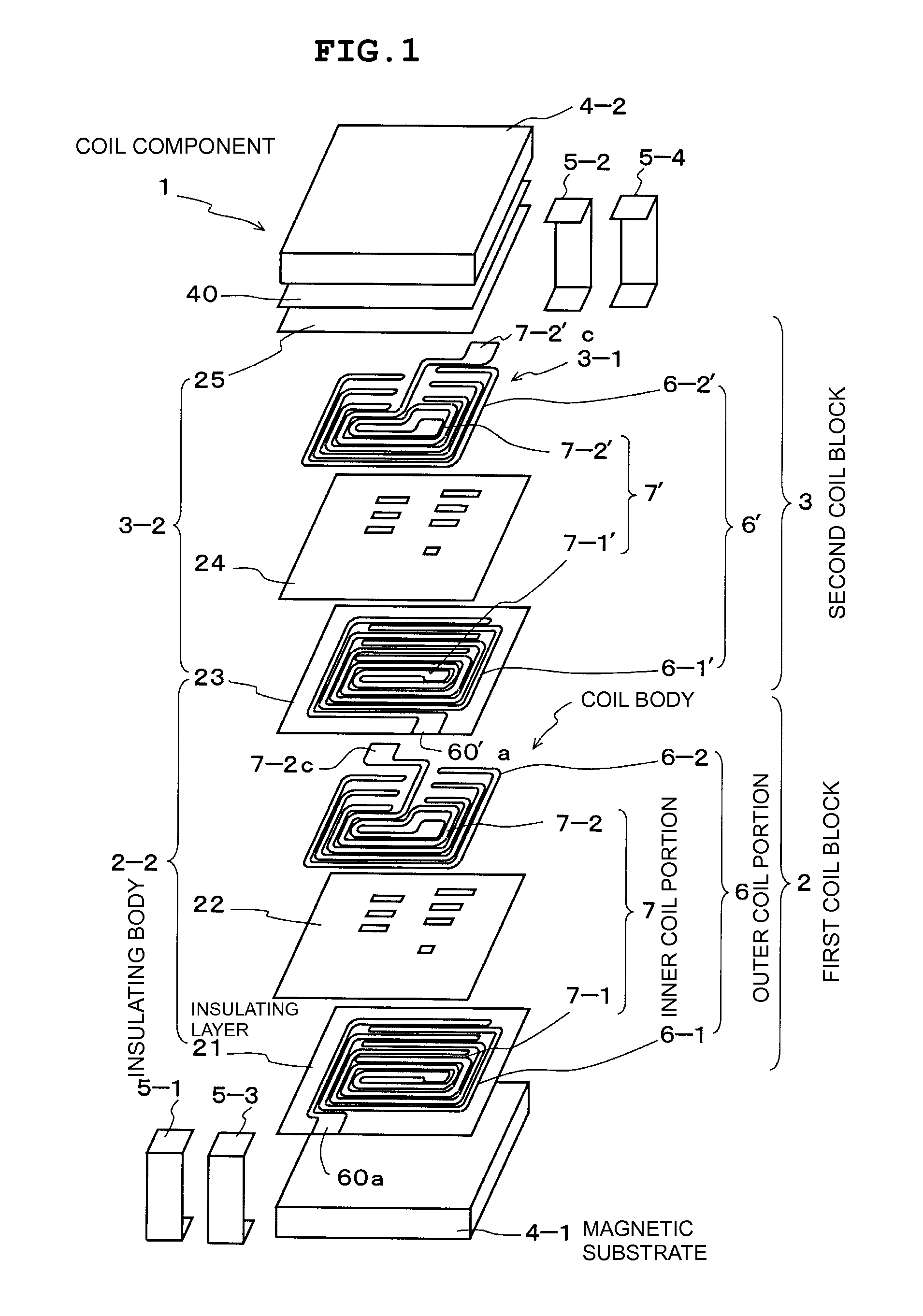
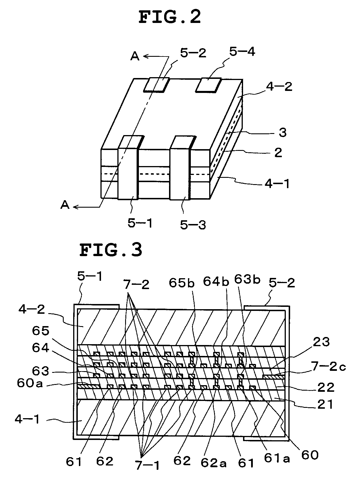
[0055]FIG. 1 is an exploded perspective view of a coil component according to a first preferred embodiment of the present invention. FIG. 2 is an external view of the coil component. FIG. 3 is a cross-sectional view taken along line A-A in FIG. 2.

[0056]The coil component according to the first preferred embodiment functions as a common-mode choke coil that is applicable to a high-speed differential transmission line of DVI standard or HDMI standard. Referring to FIGS. 1 and 2, a coil component 1 includes a first coil block 2 and a second coil block 3 that are sandwiched between a pair of magnetic substrates 4-1, 4-2 so as to form a box-shaped chip body, and four external electrodes 5-1 to 5-4 that are attached to outer surfaces of the chip body.

[0057]The first coil block 2 is provided on the magnetic substrate 4-1 and includes a single coil body 2-1 having an outer coil portion 6 and an inner coil portion 7, and an insulating body 2-2 that encompasses the coil body 2-1.

[0058]The coi...

second preferred embodiment

[0108]A second preferred embodiment of the present invention will now be described.

[0109]FIGS. 10A to 10D include plan views of a first coil block, which is a relevant portion of a coil component 1′ according to the second preferred embodiment of the present invention. FIGS. 11A and 11B include cross-sectional views illustrating an electromagnetic coupling between coil bodies.

[0110]In the second preferred embodiment, with respect to densities of pattern units including the first pattern groups 6-1 (6-1′) and the first spiral patterns 7-1 (7-1′) and densities of pattern units including the second pattern groups 6-2 (6-2′) and the second spiral patterns 7-2 (7-2′) in the coil bodies 2-1 (3-1), the second coil block 3 is stacked on the first coil block 2 such that the pattern unit with the higher density in one coil body is disposed facing the pattern unit with the higher density in the other coil body.

[0111]For example, referring to FIG. 1, the density of the pattern unit including th...


PUM

PropertyMeasurementUnit
surface roughness Raaaaaaaaaaa
sizeaaaaaaaaaa
impedanceaaaaaaaaaa

Abstract

A coil component includes a first coil block and a second coil block that are sandwiched between magnetic substrates so as to form a chip body, and external electrodes that are attached to the chip body. The first coil block includes a coil body and an insulating body. The coil body includes an outer coil portion and an inner coil portion. The outer coil portion includes a first pattern group and a second pattern group, which are connected helically vertically in an alternating fashion. The inner coil portion includes a first spiral pattern and a second spiral pattern, which are connected to each other in series. In other words, low stray capacitance is achieved by the outer coil portion, while high inductance is achieved by the inner coil portion.

Description

BACKGROUND OF THE INVENTION[0001]1. Field of the Invention[0002]The present invention relates to coil components incorporated in, for example, electronic circuits, and more particularly, to a multilayer coil component used in a high-frequency circuit.[0003]2. Description of the Related Art[0004]A typical coil component incorporated in an electronic circuit of, for example, a cellular phone is shown in FIG. 12.[0005]As shown in FIG. 12, a coil component 100 includes a multi-turn spiral pattern 101 disposed on an insulating layer 102, and an insulating layer 103 stacked on the spiral pattern 101. The insulating layer 103 includes an extending portion 104 thereon, which is connected to the spiral pattern 101 through a via hole 105.[0006]Improvements in miniaturization and high inductance in coil components are in great demand in compliance with compactness of mobile communication devices, such as cellular phones. However, with the coil component 100 having the multi-turn spiral pattern...

Claims


Application Information

Patent Timeline
Patent Type & Authority Patents(United States)
IPC IPC(8): H01F5/00
CPCH01F17/0013H01F27/323H01F27/34
Inventor MATSUNAGA, MINORUKAWAGUCHI, MASAHIKOMATSUTA, KATSUJIKUDO, KAZUHIDEITO, KENICHI
Owner MURATA MFG CO LTD
Why Eureka
Try Eureka