Vehicle locator device

a technology for locators and vehicles, applied in the direction of vehicle position/course/altitude control, process and machine control, instruments, etc., can solve the problems of difficult to find the parking location of people's vehicles upon return to their vehicles, other aids have been found, and drivers are often inconvenienced, etc., to achieve quick identification and find their vehicles, easy installation, and quick and easy attachment

Inactive Publication Date: 2008-05-06
SELLERS STEVEN +1
View PDF27 Cites 42 Cited by
  • Summary
  • Abstract
  • Description
  • Claims
  • Application Information

AI Technical Summary

Benefits of technology

[0007]In view of the shortcomings of the prior art, it is a primary object of the present invention to provide a vehicle locator device which provides a distinct visual illuminating identification signal in conjunction with a distinct audible signal, both of which are detectable from a distance of at least 1,000 feet, thereby allowing a vehicle owner to quickly identify and find their vehicle in a large, crowded parking facility in both daylight hours and at night.
[0008]It is a further object of the present invention to provide a vehicle locator device containing a flashing strobe light and an audible sound emitting device contained within a housing which is easily installed on a vehicle for long term use.
[0009]It is still a further object of the present invention to provide a vehicle locator device which provides an aerodynamic housing containing both a flashing strobe light and a sound emitting device, and wherein the aerodynamic housing is adapted for quick and easy attachment to a vehicle with the use of a double sided adhesive membrane layer (e.g. tape) that will adhere to most metallic and glass surfaces and which is adapted to withstand the rigorous demands of exterior elements (i.

Problems solved by technology

When parked in a large or unfamiliar parking facility, such as a shopping mall, airport, supermarket or stadium, people often have difficulty finding their parking location upon return to their vehicle.
In some instances, this may be a result of other parked vehicles hiding or obstructing the view of the

Method used


Image

  • Vehicle locator device
  • Vehicle locator device
  • Vehicle locator device

Examples


Embodiment Construction

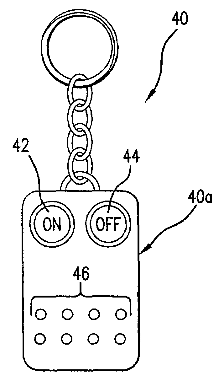
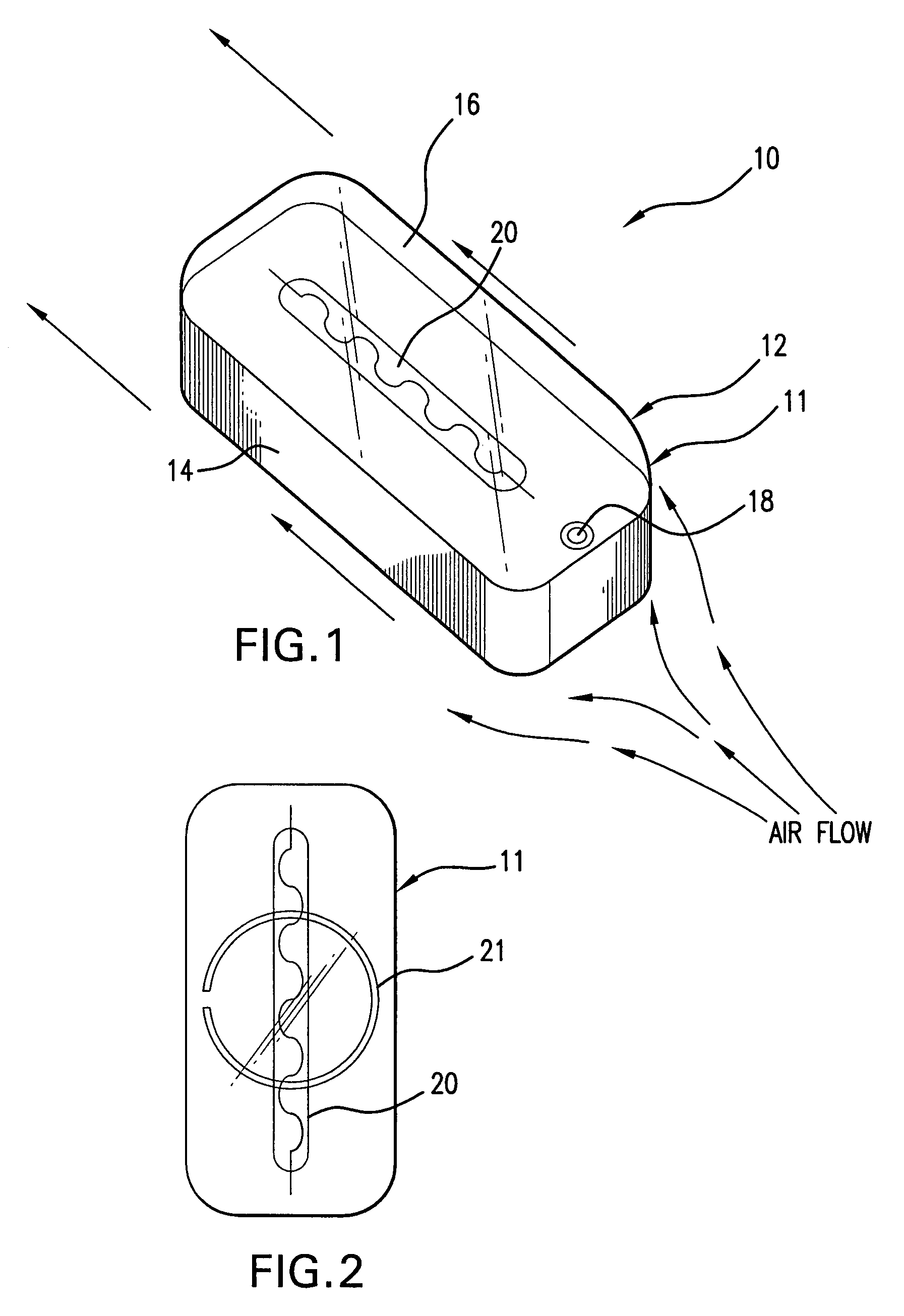
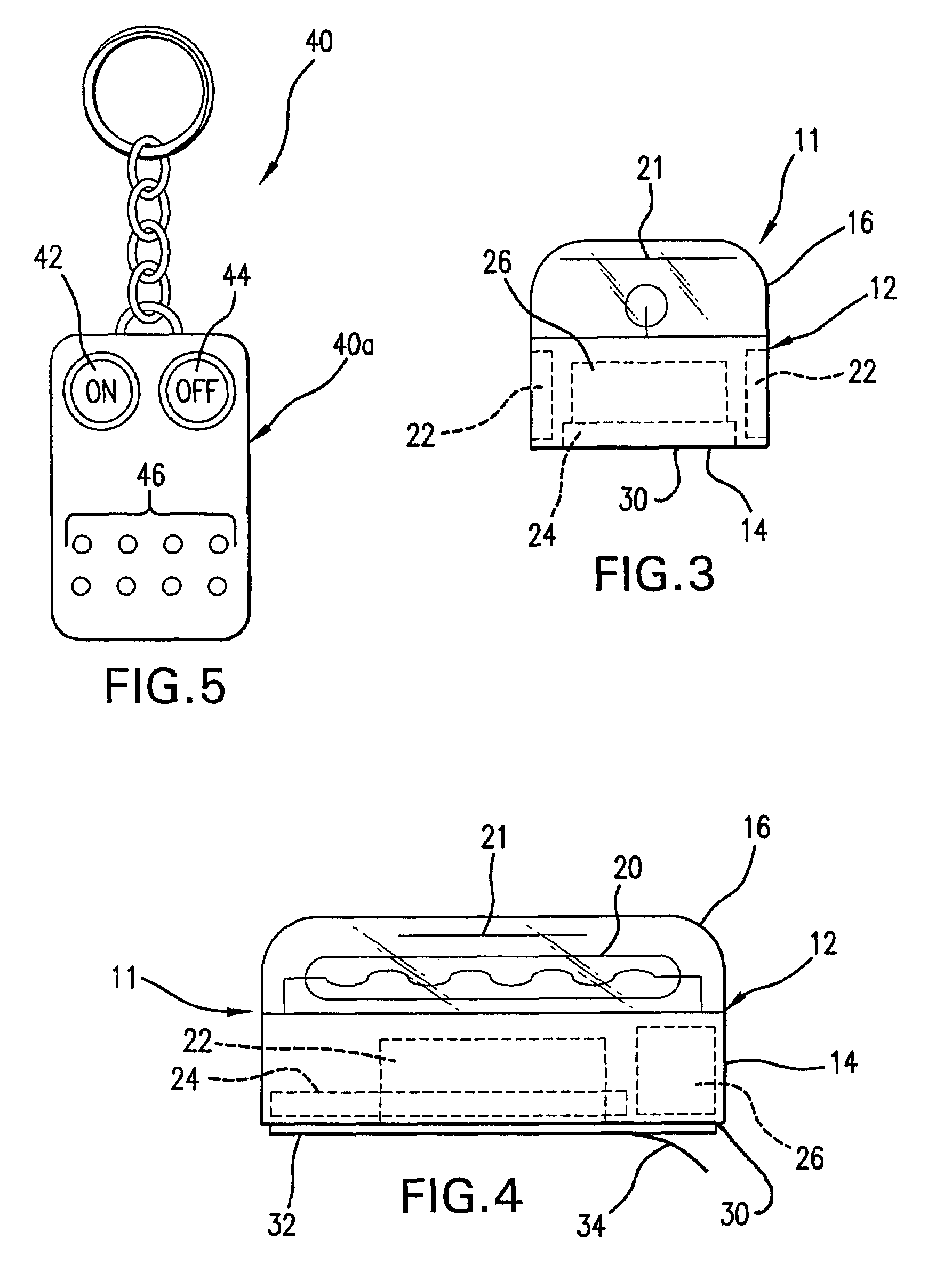
[0036]Referring to the several views of the drawings, the vehicle locator device is shown in accordance with various embodiments thereof and is generally indicated as 10. In each of the several embodiments of the invention, the vehicle locator device 10 includes a remote mobile unit (RMU) 11 and a wireless handheld unit (HHU) 40.

[0037]Referring initially to FIGS. 1-4, one embodiment of the remote mobile unit (RMU) is shown and includes a housing 12 with a base 14 and a lens cover 16. The base 14 is formed of an opaque molded plastic or like material and houses the electronic components of the device. The lens cover 16 is formed of a transparent moldable material which is UV resistant and adapted to withstand the harsh weather elements. The transparent lens cover 16 attaches to the base with two screws 18, one at each end (see FIG. 2). Attachment of the lens cover 16 to the base 14 provides a sealed enclosure to prevent penetration of water and moisture within the housing 12. A seal,...


PUM


Abstract

A device for locating a parked vehicle has a remote mobile unit with an aerodynamic housing, including a base and a transparent lens covering an illuminating visual indicator, such as a strobe light. The base contains a battery power source, an electronic sound emitter and control circuitry, including a radio signal transceiver and a spread spectrum processor. An adhesive membrane layer on the bottom of the base facilitates quick and easy attachment to a vehicle, at a location which is easily visible from a distance (e.g. the roof or other high exterior position). A wireless handheld control unit has an internal I/O processor, pushbuttons for entering commands, a spread spectrum processor and a radio transceiver and antenna for sending and receiving spread spectrum signals to and from the transceiver in the mobile unit in order to selectively activate and deactivate the illuminating visual indicator and sound emitter. The distinct emitted sound and flash sequence and/or rhythm of the illuminating indicator can be selectively programmed and/or changed by the user with the wireless handheld unit. The sound emitter and illuminating indicator have a respective audible and visual range of at least 1,000 feet.

Description

[0001]This application claims priority from U.S. Provisional Application No. 60 / 616,581 entitled Vehicle Locator Device, filed on Oct. 5, 2004.BACKGROUND OF THE INVENTION[0002]1. Field of the Invention[0003]The present invention relates generally to devices that aid in the location of an automobile parked in a large and / or crowded parking lot or garage. More particularly, the present invention relates to a device for aiding in finding the location of a parked automobile with the combined usage of both a distinct illuminating visual indicator and a district audible indicator detectable from a range of at least 1,000 feet, and wherein both the illuminating indicator and audible indicator can be selectively changed to provide user specific visual and audible signals detectable during daylight and nighttime hours.[0004]2. Discussion of the Related Art[0005]When parked in a large or unfamiliar parking facility, such as a shopping mall, airport, supermarket or stadium, people often have d...

Claims


Application Information

Patent Timeline
IPC IPC(8): B60Q1/48
CPCB60Q1/482
Inventor SELLERS, STEVENSELLERS, ALEXA
Owner SELLERS STEVEN
Why Eureka
Try Eureka