Differential current-steering digital-to-analog converter

a current-steering and digital-to-analog converter technology, applied in the field of digital-to-analog converters, can solve problems such as large total error, error in output levels, and two currents that may not be exactly matched, and achieve the effect of reducing noise conversion

Inactive Publication Date: 2008-05-06
INTEL CORP
View PDF5 Cites 12 Cited by
  • Summary
  • Abstract
  • Description
  • Claims
  • Application Information

AI Technical Summary

Benefits of technology

[0030]In embodiments the switching control circuitry comprises a pair of switches, one switch for each current generator of the pair of current generators. The ternary signal may then comprise a pair of binary bits on two control lines, one for each switch. The code converter to translate between the binary digital input and the control inputs of the steerable current generators, that is the ternary control signals, may either be implemented using a look-up table or using logic. As will be seen later, the patterns to be generated are relatively straightforward and approximate simple counting so that an implementation in combinatorial logic may be relatively simple and straightforward.
[0039]The invention still further provides a method of reducing noise when converting a digital signal to an analogue signal, said analogue signal having a range of values and signal characteristics defining, on average, time spent by said signal in a first part of said range relative to time spent in a second part of said range, said time spent by said signal in said first part of said range being greater than said time spent by said signal in said second part of said range, the method comprising reshaping a differential non-linearity error pattern of said conversion to move a proportion of differential non-linearity error from said first range to said second range of said analogue signal to thereby reduce said noise of said converting.
[0041]In a related aspect the invention provides a converter for reduced noise converting of a digital signal to an analogue signal, said analogue signal having a range of values and signal characteristics defining, on average, time spent by said signal in a first part of said range relative to time spent in a second part of said range, said time spent by said signal in said first part of said range being greater than said time spent by said signal in said second part of said range, said converter being configured to reshape a differential non-linearity error pattern of said conversion to move a proportion of differential non-linearity error from said first range to said second range of said analogue signal to thereby reduce said noise of said converting.

Problems solved by technology

This produces errors in the output levels.
This means that all the errors added together, and the total error can be very large.
However, the worst-case static error in the DAC is at the transition from 127 to 128 and this centres the signal at the worst possible place in the transfer function.
In practice, however, the two currents may not be exactly matched and because of this there may be a small difference in the differential output between steering the first current to the first differential output line and the second current to the second differential output line and the first current to the second differential output line and the second current to the first differential output line.
In this way the errors may be noise coded to reduce their effect.
Although additional switches and some code conversion logic is required, the overall increase in size and power consumption (from the switching) need not be large.

Method used


Image

  • Differential current-steering digital-to-analog converter
  • Differential current-steering digital-to-analog converter
  • Differential current-steering digital-to-analog converter

Examples


Embodiment Construction

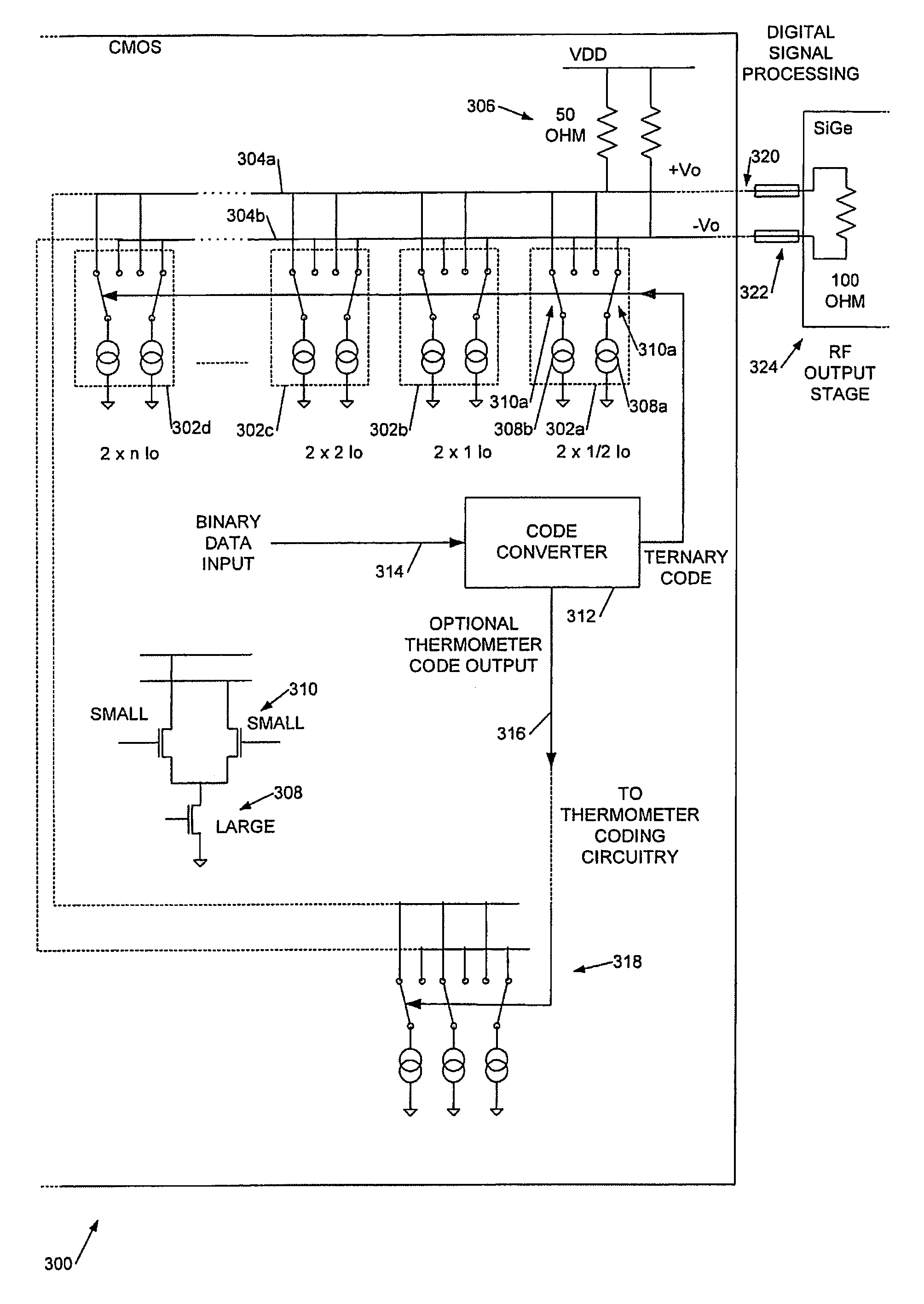
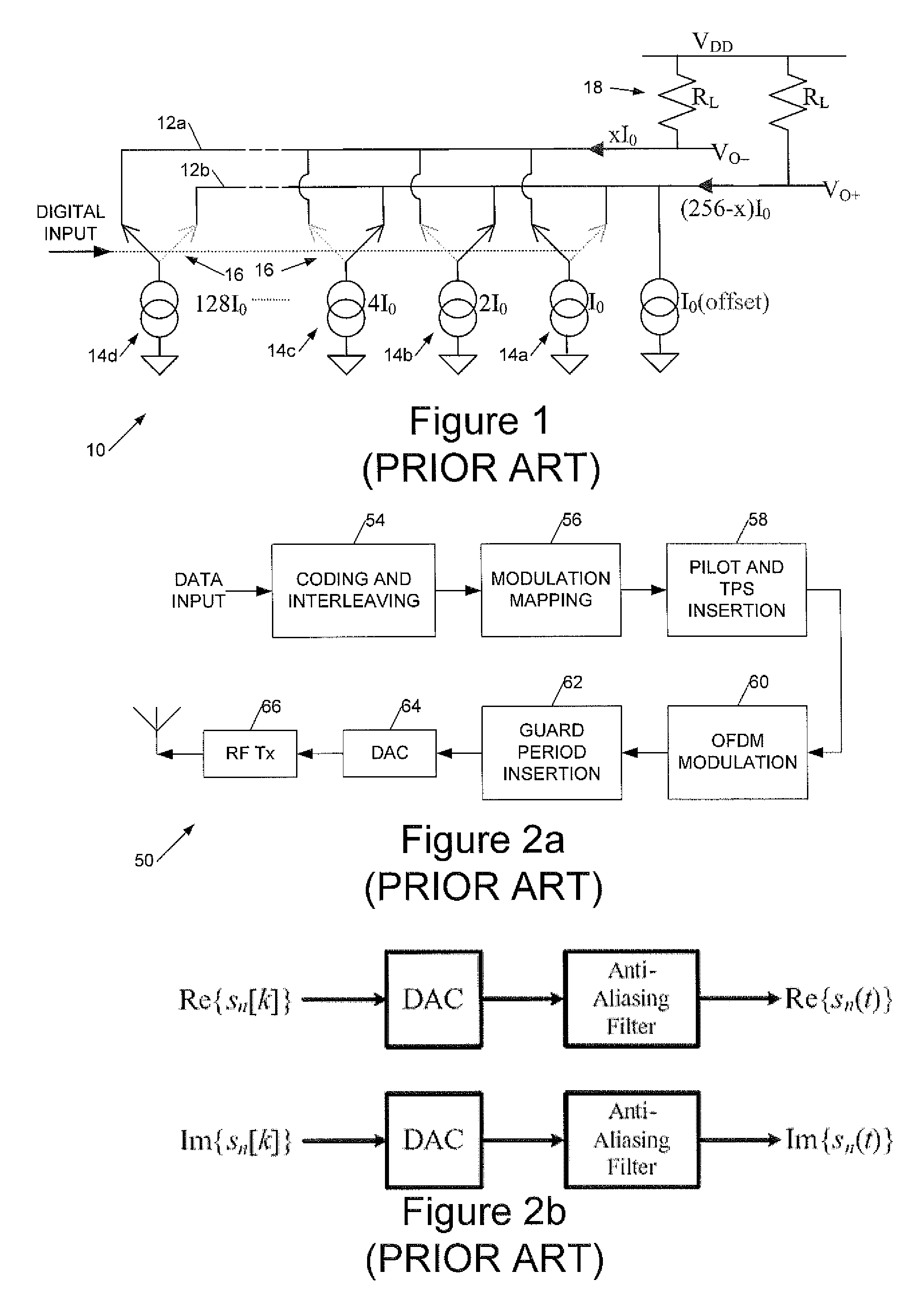
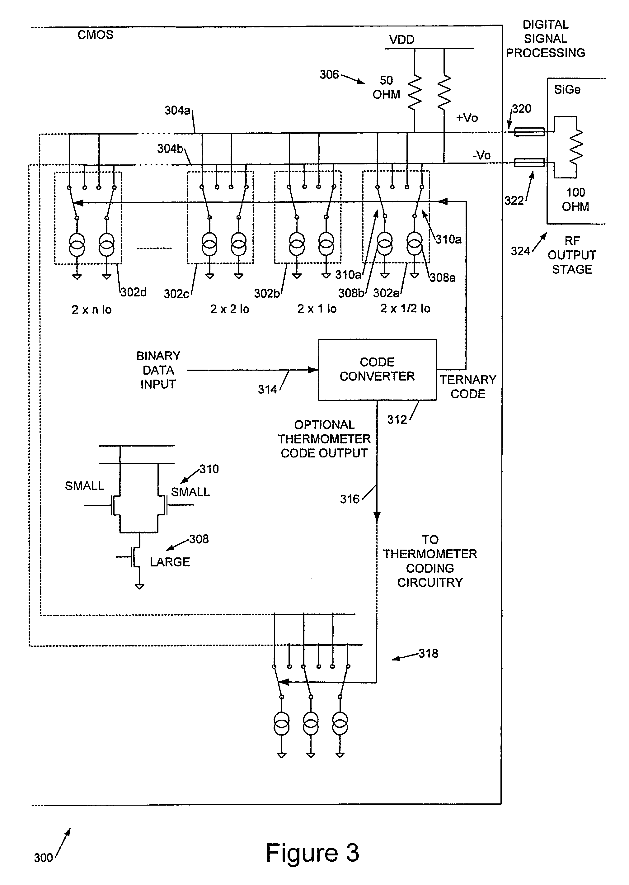
[0049]Broadly speaking we will describe a current-steering DAC in which a major transition for small signals at the zero point of a differential output is avoided, albeit at the cost of a slightly reduced negative range, for example from −128 to −127 for an 8-bit DAC. We will describe how the MSB transition may be avoided by rearranging the switches so that all the currents substantially cancel at the centre of the range. Further, the switches are arranged so that LSB switches are used to create small, preferably the smallest possible steps (transition-related errors) when moving away from the centre (0) of the range. Still further away from the centre, the MSB switches are toggled; this potentially creates larger errors but these are now out of the normal operating range, for example of an OFDM signal, or at least in a place where the signal is larger. The DAC is also useful in other RF communication systems for converting digitised to analogue RF, in particular in a transmitter.

[0...


PUM


Abstract

Differential, current-steering DACs with reduced small signal differential non-linearity. A set of binary-weighted steerable constant current generators is used in which each constant current generator comprises a ternary constant current generator configured to generate a three-state differential current in response to a ternary signal on a control input. Each ternary current generator is associated with a bit of the binary code. The DAC further comprises a code converter coupled between a digital input, to receive a signed digital value for conversion, and control inputs of the steerable current generators, to convert the binary input code to a ternary code to control the steerable current generators to provide a differential analogue output. In embodiments the smallest current source is ½I0 where I0 is a change in differential output current caused by an lsb change in the binary input code.

Description

CROSS REFERENCE TO RELATED APPLICATIONS[0001]This application claims benefit under 35 U.S.C. §119 to UK Application No. 0608375.2, filed Apr. 28, 2006, and to U.S. Provisional Patent Application No. 60 / 795,639, filed Apr. 28, 2006, which are both incorporated herein by reference in their entireties.BACKGROUND[0002]1. Field of the Invention[0003]This invention generally relates to digital-to-analogue converters (DACs). More particularly it relates to differential, current-steering DACs with reduced small signal differential non-linearity.[0004]2. Related Art[0005]Background references relating to current-steering DACs can be found in: US2003227402; US6853323; WO03021790; US6507304; US2003 / 001765; US2006 / 0012501; U.S. Pat. No. 6,967,609; WPO 2005 / 117402; US2005 / 0225465; U.S. Pat. No. 6,927,714; U.S. Pat. No. 6,833,801; US2004 / 0119621; U.S. Pat. No. 6,720,898; U.S. Pat. No. 6,703,956; U.S. Pat. No. 6,741,195; US2003 / 112164; US2003 / 001656; WO0215421; US2002 / 030619; U.S. Pat. No. 6,339,3...

Claims


Application Information

Patent Timeline
Patent Type & Authority Patents(United States)
IPC IPC(8): H03M1/80
CPCH03M1/0695H03M1/687H03M1/745
Inventor CARROLL, BRIAN STEPHEN
Owner INTEL CORP
Why Eureka
Try Eureka