Portable refractometer

a refractometer and portable technology, applied in the field of portable refractometers, can solve the problems of inability to apply a small model configuration, inability to accurately perform temperature compensation, and inability to accurately measure the degree of change of the objective lens in response to temperature changes, etc., to achieve accurate temperature compensation

Inactive Publication Date: 2008-05-06
ATAGO
View PDF17 Cites 14 Cited by
  • Summary
  • Abstract
  • Description
  • Claims
  • Application Information

AI Technical Summary

Benefits of technology

[0010]With the foregoing in view, it is an object of the present invention to provide a portable refractometer that is capable of accurately performing temperature compensation.

Problems solved by technology

A problem arises as when a user holds the refractometer 200 for a long period the planar bimetal 214 undergoes shape transformation in response to the heat of the hand of the user, thereby inhibiting temperature compensation from being performed accurately.
Moreover, as substantial space is required inside the lens barrel 216 this configuration cannot be applied for a small model, portable refractometer.
In the same way as the portable refractometer shown in FIG. 2 however, a cantilever arrangement is used in which a long thin planar member that changes in shape in response to changes in temperature supports the objective lens, thus the degree of change of the objective lens in response to changes in temperature is unstable and temperature compensation cannot be performed accurately.
Further, in the same manner as the portable refractometer shown in FIG. 2, a large number of components are used for this arrangement making assembly complicated and mitigating against miniaturization.

Method used


Image

  • Portable refractometer
  • Portable refractometer
  • Portable refractometer

Examples


Embodiment Construction

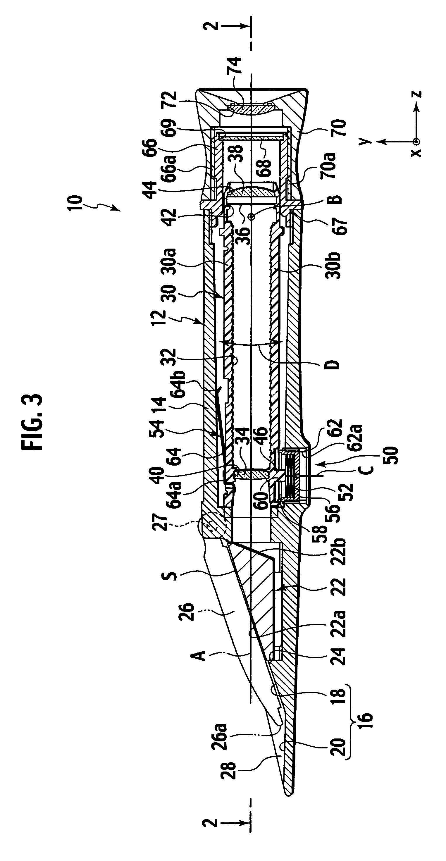
[0039]An embodiment of the present invention will now be described with reference to FIGS. 3 to 11. In these drawings, like reference numerals identify like elements.

[0040]FIG. 3 is a cross-sectional view of an embodiment of a portable refractometer according to the present invention cut in the vertical direction along the optical axis. FIG. 4 is a cross-sectional view of the portable refractometer shown in FIG. 3 cut in the horizontal direction along the optical axis.

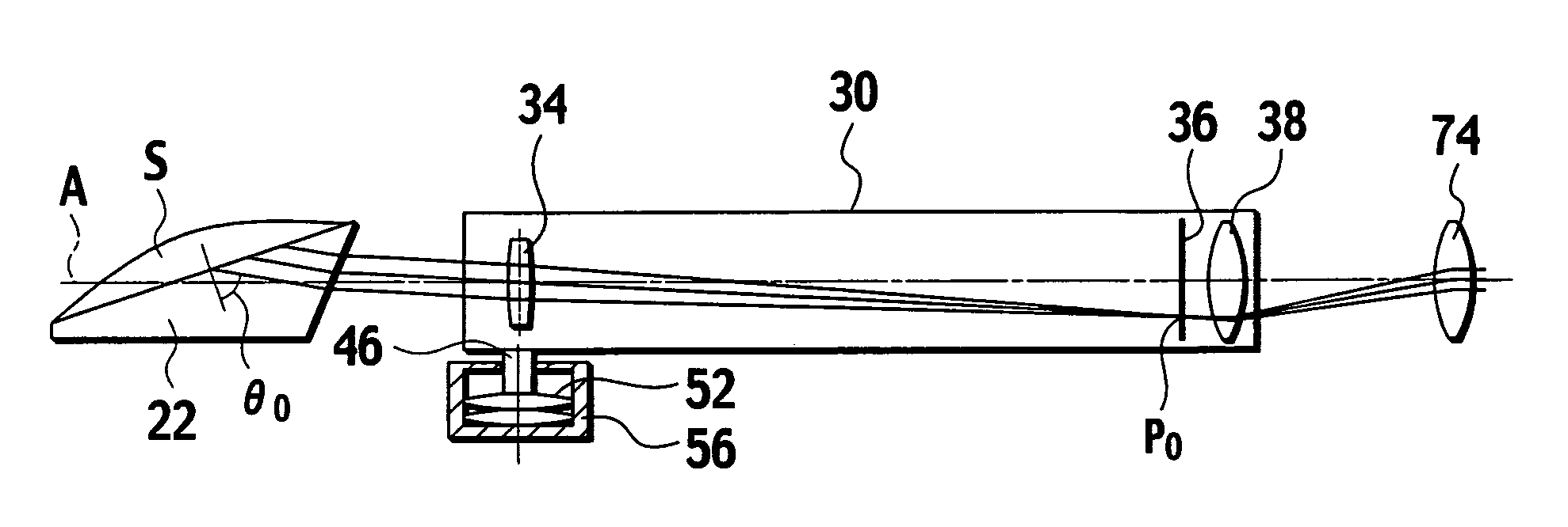
[0041]As shown in FIG. 3 the portable refractometer 10 comprises: a lens barrel 12 having a lens barrel axis A; a prism 22 secured to the front end of the lens barrel 12; an optical chassis 30 rotatably supported about a predetermined rotational axis inside the lens barrel 12; an objective lens 34 arranged in a forward position inside the optical chassis 30; an optical scale 36 arranged in a rearward position inside the optical chassis 30; and a moving means 50 that moves the objective lens 34 relatively relative to th...


PUM

PropertyMeasurementUnit
temperatureaaaaaaaaaa
index of refractionaaaaaaaaaa
temperatureaaaaaaaaaa

Abstract

A portable refractometer is provided that includes a lens barrel having a lens barrel axis. A prism is secured to one end of the lens barrel, the prism having an entry face that provides a boundary surface between the prism and a substance to be measured. A tube shaped optical chassis is inside the lens barrel, and is rotatably supported about a predetermined rotational axis perpendicular to the lens barrel axis. An objective lens is arranged in the optical chassis, and is positioned in relation to the optical chassis. An optical scale is arranged inside the optical chassis, at the focal point of the objective lens. A mover moves the objective lens relatively in relation to the optical scale in response to changes in temperature by turning the optical chassis about the rotational axis.

Description

[0001]This application claims benefit of priority to Japanese Patent Application No. 2005-020194, filed on Jan. 27, 2005, the entire contents of which are incorporated by reference herein.BACKGROUND OF THE INVENTION[0002]1. Field of the Invention[0003]The present invention relates to a portable refractometer for measuring the refractive index of a liquid.[0004]2. Description of Related Art[0005]Portable refractometers for measuring the index of refraction of a liquid are known in conventional technology. A portable refractometer measures the index of refraction of a liquid from a critical angle at the boundary surface or interface between the liquid and a prism the index of refraction of which is already known. Because the index of refraction of a liquid changes according to the content of soluble material, generally, a portable refractometer is used as a density measuring meter (densitometer) or sugar concentration measuring meter for measuring the density or sugar concentration of...

Claims


Application Information

Patent Timeline
Patent Type & Authority Patents(United States)
IPC IPC(8): G01N21/41
CPCG01N21/431G01N21/43G01N2201/0221B01D21/2461B08B5/02C02F1/40
Inventor AMAMIYA, HIDEYUKIAMAGASA, YASUHIKOKUBODERA, TAKESHIMURATA, MITSURU
Owner ATAGO
Why Eureka
Try Eureka