Image reversion system, ancillary ophthalmoscopy module and surgical microscope

Inactive Publication Date: 2008-05-06
CARL ZEISS SMT GMBH
View PDF18 Cites 4 Cited by
  • Summary
  • Abstract
  • Description
  • Claims
  • Application Information

AI Technical Summary

Benefits of technology

[0012]It is an object of the invention to provide a system for image reversion with a reduced structural elevation which can be used in an ancillary module for a surgical microscope wherein the ancillary module is designed for carrying out surgery in the rear section

Problems solved by technology

Only a relatively small work space is available to an operator when utilizing such an ophthalmoscopic ancillary module in a surgical microscope.
Such ophthalmoscopic ancillary modules are not designed for contact lenses with which the ocular fundus can be made visible in correspondence to an ophthalmoscopic magnifier for which a comparatively large work space is possible for the operator.
However, there is a clear brightness loss of the image seen by the main and assistant viewers.
This leads to a correspondingly high look-in elevation and a surgeon can only assume an unfavorable wo

Method used


Image

  • Image reversion system, ancillary ophthalmoscopy module and surgical microscope
  • Image reversion system, ancillary ophthalmoscopy module and surgical microscope
  • Image reversion system, ancillary ophthalmoscopy module and surgical microscope

Examples


Embodiment Construction

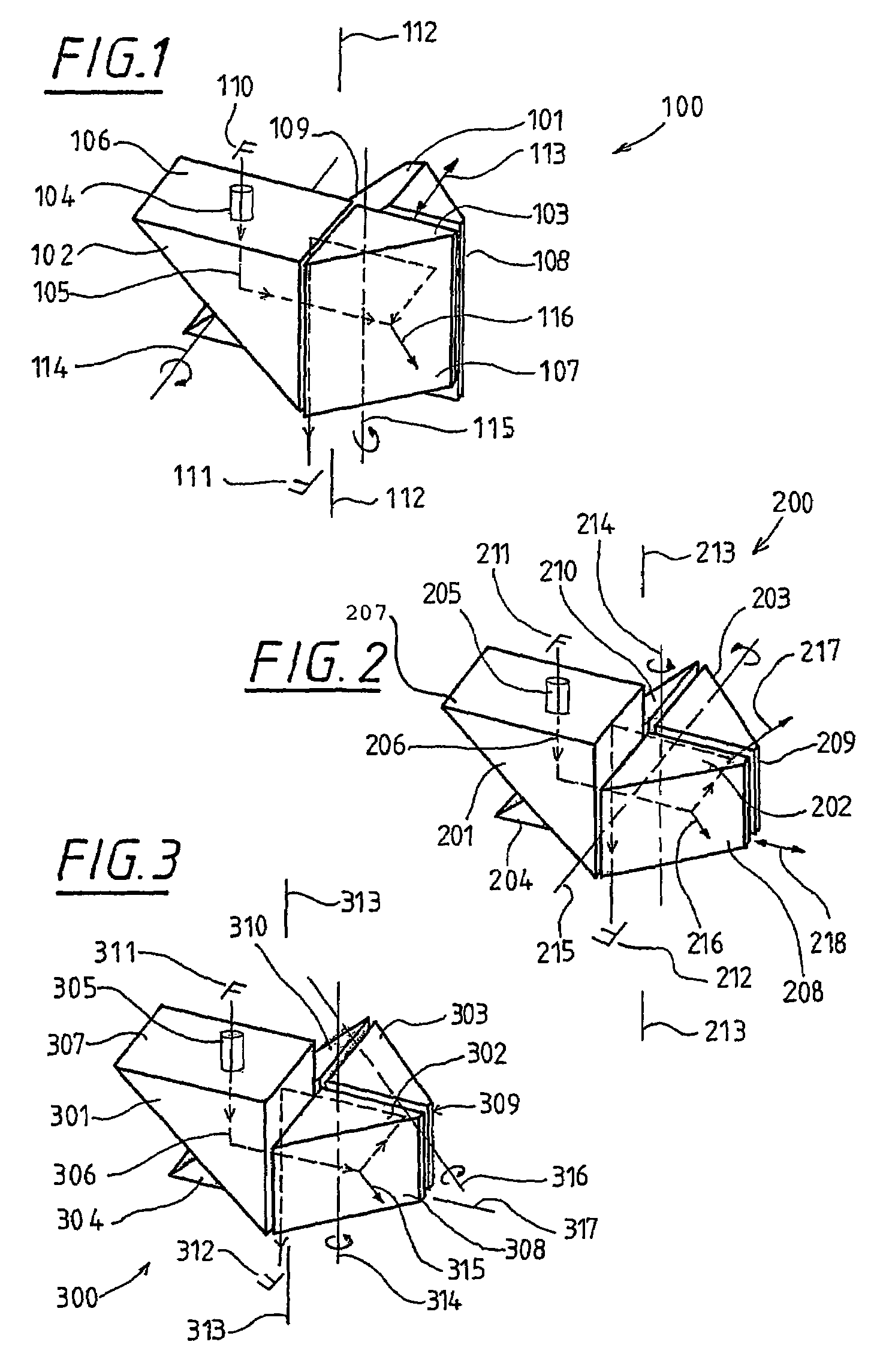
[0041]The system for image reversion 100 of FIG. 1 comprises a component prism 101 to which two 90° prisms 102 and 103 are assigned. As the special case of a Porro prism, the component prism 101 is configured as a half, shortened Porro prism of the second type. An incident beam 104 having a beam path 105 passes through the side surface 106 of the component prism 102 and is reflected at the side surface, which lies opposite the 90° angle and acts as a mirror, and is deflected from its incident direction toward the 90° prism 103 with this direction being transverse to the incident direction. In the 90° prism 103, the total reflection at the side surface 107, which acts as a mirror, leads to the deflection of the beam path into the component prism 101. After reflection at the side surfaces 108 and 109 of component prism 101, the companion viewing beam path passes laterally offset through the base surface of the component prism 101. The side surfaces 108 and 109 operate as mirrors.

[0042...


PUM


Abstract

The invention relates to an image reversion system (500) which enables an image reversion and beam transposition of a plurality of observation beam paths (503a, 503b, 504a and 504b) to be carried out simultaneously. The system includes at least one Porro prism system and is designed in such a way that it can be arranged in a convergent beam path. The inventive system is suitable as an image reversion system in an ancillary module for operational microscopes used in ophthalmoscopy due to the low overall height thereof.

Description

RELATED APPLICATIONS[0001]This application is a continuation application of international patent application PCT / EP 01 / 10094, filed Sep. 1, 2001, and claiming priority from German patent applications 100 47 617.1, filed Sep. 26, 2000, and 101 40 402.6, filed Aug. 17, 2001.FIELD OF THE INVENTION[0002]The invention relates to a system for image reversion having a first mirror for deflecting a beam from an incident direction into a first direction which runs tranversely to the incident direction. The image reversion system further includes a second mirror for deflecting the beam, which was deflected at the first mirror, into a second direction which is transverse to the first direction and a third mirror for deflecting the beam, which is deflected at the second mirror, into a third direction which is transverse to the second direction and a fourth mirror for deflecting the beam, which is deflected by the third mirror, into a direction which is transverse to the third direction. The fir...

Claims


Application Information

Patent Timeline
IPC IPC(8): G02B21/18A61B19/00G02B5/04G02B17/04G02B21/00G02B21/02G02B21/22
CPCG02B5/04G02B17/045G02B21/0012G02B21/025G02B21/18G02B21/22A61B19/5223A61B90/20
Inventor STRAEHLE, FRITZREIMER, PETERGOTTWALDT, KLAUSMERZ, FRANZ
Owner CARL ZEISS SMT GMBH
Why Eureka
Try Eureka