Neuro-navigation system

a navigation system and neuronal technology, applied in the field of neuronal navigation system, can solve the problems of no longer being able to precisely position, no longer being able to access the precise position, and known landmarks, once affixed to the patient, no longer being removable, etc., and achieve the effect of accurate positioning

Inactive Publication Date: 2005-09-15
BRAINLAB
View PDF45 Cites 20 Cited by
  • Summary
  • Abstract
  • Description
  • Claims
  • Application Information

AI Technical Summary

Benefits of technology

[0023] It is thus the object of the present invention to provide a Neuro-navigation system which overcomes the cited drawbacks of prior art by, more particularly, substantially facilitating mapping the locations of surgical instruments and apparatus employed in the operation as well as referencing the anatomy of the patient and the operation apparatus with the aid of the Neuro-navigation system in accordance with the invention or with more accurate positioning. It is furthermore intended to make it possible to integrate a surgical microscope, an ultrasonic diagnostic system as well as a procedure for calibrating the camera position in a Neuro-navigation system.

Problems solved by technology

This is followed by a time-consuming step in which the surgeon needs to access the individual landmarks on the patient with a pointer, he then having to enter into the computer which of the identical landmarks in the operating position correspond to those sensed in the computer tomography.
Since the landmarks secured by sticky plaster fail to comprise characteristical reference points, which cannot be missed in accessing them with an instrument tip, mapping in this respect can only take place relatively inaccurately.
A further disadvantage in this respect is that the conventional landmarks, once covered with sterile cloths, are no longer directly discernible, because of their flat configuration, and thus can no longer be accessed precisely in position should the patient already be covered.
This causes problems particularly later on when the position of the patient is changed during the operation and the landmarks need to be reaccessed with the pointer for a readjustment.
Furthermore, it is a disadvantage that the known landmarks, once affixed to the patient, are no longer removable by being able to be replaced by other landmarks in precisely the same position.
This conventional instrument referencing system is also hampered by several drawbacks as explained in the following.
Using active, i.e. self-emitting signal transmitters already has the disadvantage that electronic means need to be provided in the instruments which makes particularly the manufacture of such instruments more expensive.
In addition, the cables attached to each instrument connecting it to the computer unit are an obstruction to movement and can get in the way during the operative treatment due to the many instruments often to be used.
Sterilization of such instruments can only be done by gas sterilization.
One serious drawback of the conventional referencing system is that the surgeon is only able to use exclusively the instruments made available by the system manufacturer.
Many surgeons are, however, used to their own set of instruments and need to adapt when using another specified set of instruments which may have a negative effect on the outcome of the operation.
It is a disadvantage that conventional Neuro-navigation systems fail to provide a simple calibration system with which the angles or spacing of the mapping or referencing cameras can be mapped or recalibrated at any time without complication.
Microscopes are namely conventionally unable to output any additional position feedback signals to the Neuro-navigation computer other than the positional data resulting from the position of the arm.
It has hitherto been a drawback in the case of conventional systems that although the position of the sensed parts of the body could be related to the ultrasonic emitter and detector, there was no possibility of simply assigning this data to a Neuro-navigation system made available on the operating table.

Method used


Image

  • Neuro-navigation system
  • Neuro-navigation system
  • Neuro-navigation system

Examples


Embodiment Construction

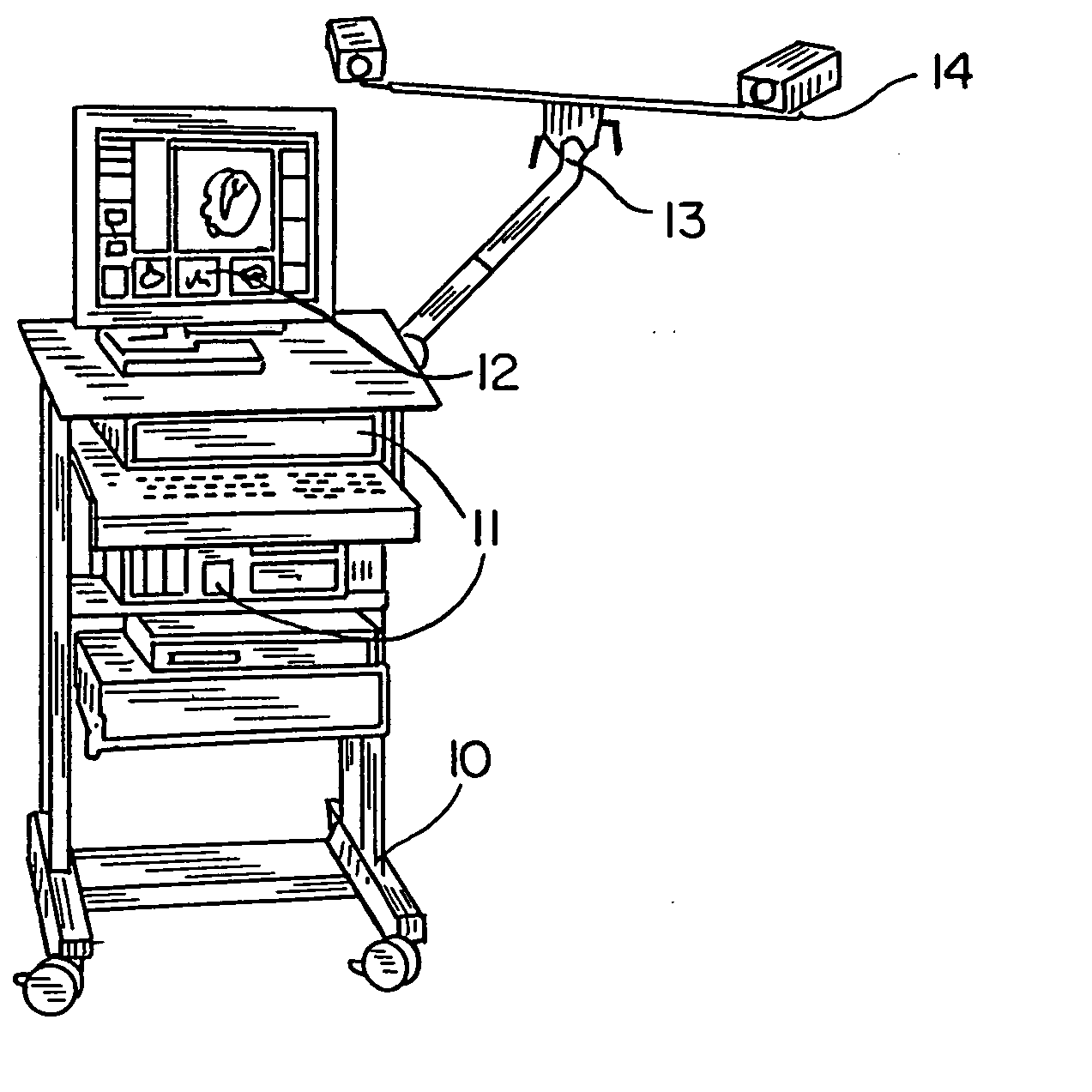
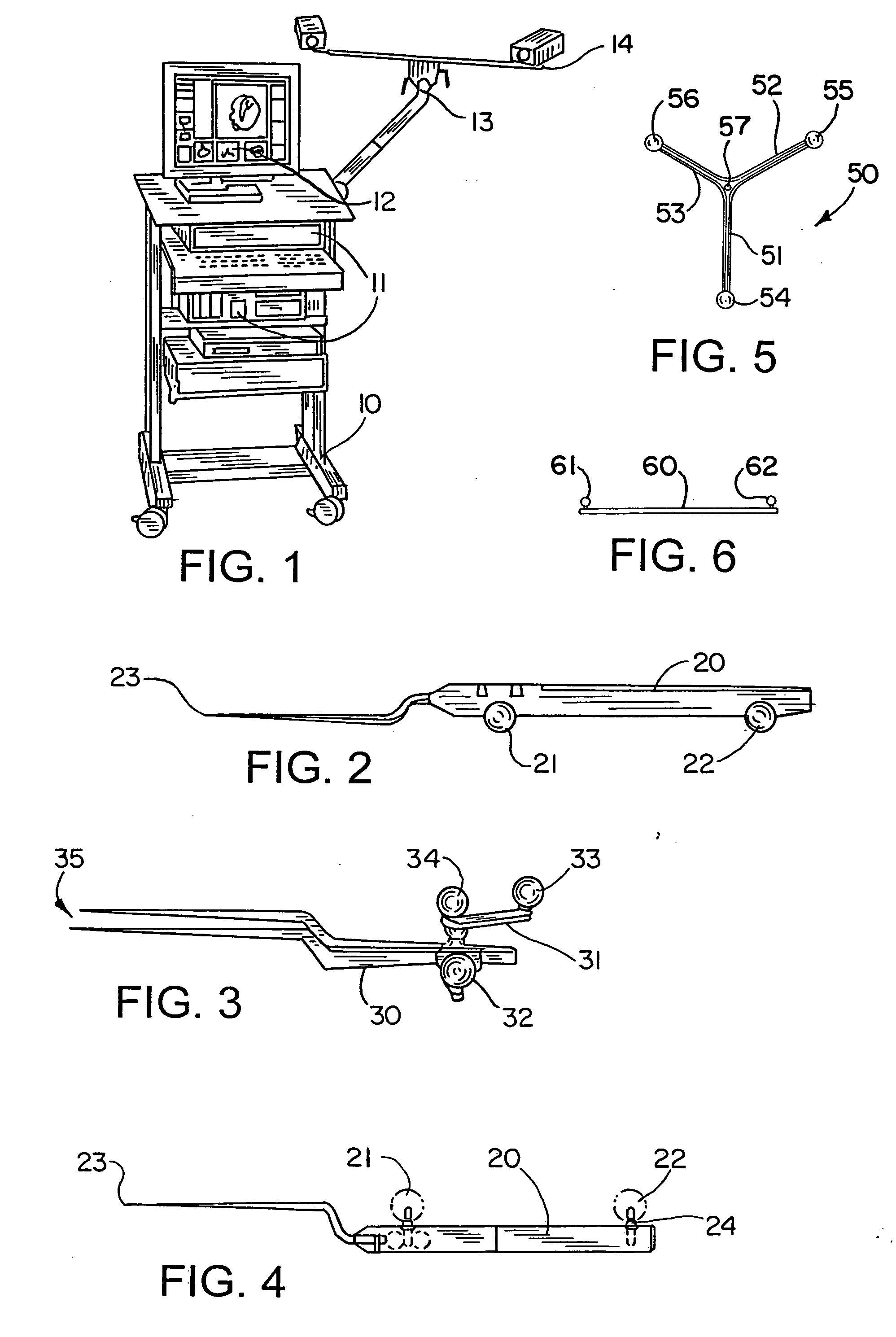
[0080] In an operating theater in which the Neuro-navigation system in accordance with the invention is put to use, a frame as identified by the reference numeral 10 in FIG. 1 stands, for example, at one end of an operating table. Accommodated in this frame is a computer unit 11 and various other control units such as, for example, a keyboard (not identified). Connected to this computer unit is the monitor 12 placed on the frame. This monitor displays in various views, also in a three-dimensional view, section planes or images of the anatomy of the patient, it also showing the positions of surgical instruments or reflectors attached to these instruments and to the operation apparatus. Additional information may be output in further fields on the screen.

[0081] Likewise secured to the upper part of the frame, on which the monitor 12 stands, is the camera mount 13. This camera mount 13 is configured adjustable and carries at the ends of its upper arms two infrared cameras, identified ...


PUM


Abstract

The invention relates to a Neuro-navigation system comprising a reflector referencing system including passive reflectors and a marker system with markers or landmarks wherein the reflectors as well as the markers as regards their shape, size and material selection as well as their arrangement or attachment on the parts of the body to be operatively treated and on the surgical instruments are configured so that mapping their locations is substantially facilitated or is able to take place more accurately positioned by a computer / camera unit having a graphic display terminal as well as the operative treatment with the aid of this unit. Optionally a surgical microscope, an ultrasonic diagnostic system as well as a calibration procedure may be integrated in the Neuro-navigation system in accordance with the invention.

Description

[0001] This application is a divisional of U.S. patent application Ser. No. 10 / 083,041 filed on Feb. 26, 2002 which is a divisional of U.S. patent application Ser. No. 09 / 695,130 filed Oct. 24, 2000, which is a divisional of Ser. No. 08 / 919,454 filed Aug. 28,1997 now U.S. Pat. No. 6,351,659, which is a continuation in part of 08 / 713,212 filed Sep. 12, 1996 now U.S. Pat. No. 5,769,861, all of which are hereby incorporated herein by reference in their entirety.BACKGROUND OF THE INVENTION [0002] 1. Field of the Invention [0003] The invention relates to a neuro-navigation system comprising a reflector referencing system including passive reflectors and a marker system with markers or landmarks wherein the reflectors as well as the markers as regards their shape, size and material selection as well as their arrangement or attachment on the parts of the body to be operatively treated and on the surgical instruments are configured so that mapping their locations is substantially facilitate...

Claims


Application Information

Patent Timeline
Patent Type & Authority Applications(United States)
IPC IPC(8): A61B6/00A61B6/12A61B17/00A61B19/00G02B21/32
CPCA61B6/12A61B8/0808A61B6/583A61B19/20A61B19/52A61B19/5223A61B19/5244A61B19/56A61B2017/0046A61B2019/507A61B2019/5255A61B2019/5263A61B2019/5268A61B2019/5272A61B2019/5287A61B2019/5425A61B2019/547A61B2019/5483G02B21/32A61B6/4405A61B34/20A61B34/25A61B90/10A61B90/20A61B90/36A61B2034/107A61B2034/2055A61B2034/2063A61B2034/2068A61B2034/2072A61B2090/363A61B2090/3925A61B2090/397A61B2090/3983
Inventor VILSMEIER, STEFAN
Owner BRAINLAB
Why Eureka
Try Eureka