[0007]The invention is based on the object, against the background of the prior art as cited above, of providing a wind energy installation and a method for alignment of the wind energy installation, which allows more accurate alignment, even in difficult conditions, with little complexity.
[0011]One major aspect is based on the use of a specialized element to form an efficiency measure. The efficiency measure is an indicator of the magnitude of the actual output of the wind energy installation in the given wind conditions, that is to say how well it makes use of the wind. The efficiency measure results in the controller being independent of influences which are caused by changes in the
wind speed. Various physical variables may be used as a quantity for the efficiency measure. This will frequently be the electrical power. However, it is also possible to use the electrical energy that is generated. This has the
advantage that, when a measurement is carried out over a
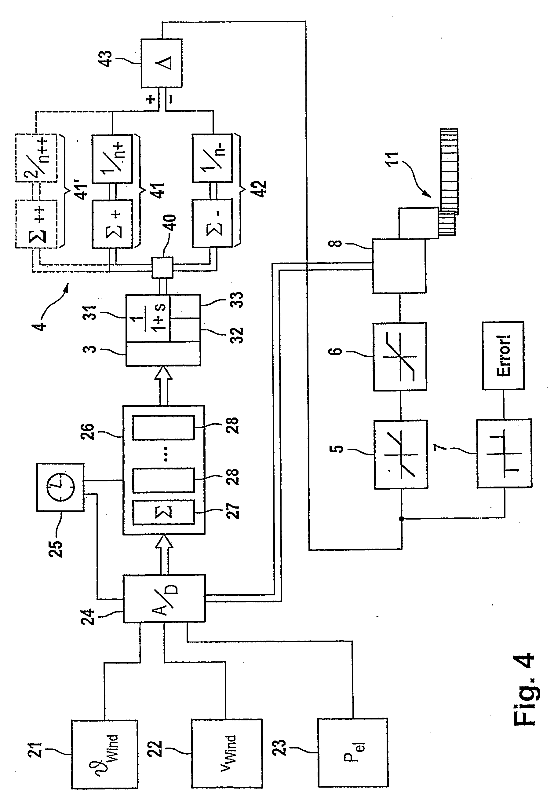
specific time period, brief fluctuations are compensated for automatically by the integration associated with this. However, other variables can also be used, such as the electrical torque of the generator or the mechanical torque passed from the rotor to the generator, or to an intermediate transmission. The efficiency measure element is preferably in the form of a normalization element, which is designed to normalize the quantity with respect to the
wind speed. This is expediently done in the simplest form by forming the ratio of the electrical power to the third power of the wind speed. This makes it possible to eliminate the influence of varying wind speeds. The invention can even take account of those errors which occur as a result of wind direction shifts resulting from a freshening wind. The quality of the
azimuth position is therefore considerably improved.
[0013]The efficiency measure element preferably additionally has a
system model of the rotor / generator
system. The
system model includes system knowledge relating to the mechanical and electrical behaviour of the rotor / generator system for conversion of
mechanical energy to electrical energy, in the form of a
mathematical model. In this case, particular account is also taken of influencing variables such as
inertia of the rotor / generator system. A model such as this can be used to improve the quality of the efficiency measure that is formed since even a rotor rotation speed which varies only slowly under the influence of gusts can be recorded appropriately. The model can intrinsically be designed as required. However, it has been found to be advantageous for it to be in the form of a first-order
delay element. This allows the system behaviour to be approximated well with comparatively little effort. It is also possible to provide for the
system model to map the system behaviour, in terms of different efficiency levels of the wind energy installation. By way of example, the efficiency levels differ in different operating ranges of the wind energy installation. The efficiency level in the region of the optimum tip-speed ratio is higher than in the upper constant rotation speed control range, and is also, once again, different from the efficiency level in the lower power range. A
system model configuration such as this makes it possible to refine the mapping of the system behaviour.
[0015]The efficiency measure element is preferably designed to be self-adapting. This makes it possible for it to autonomously match itself to varying location-dependent or wind-condition-dependent factors. This is particularly advantageous when
distortion occurs in the case of winds from one specific direction, leading to incorrect measurements of the wind direction via the weathervane, or for which the wind is not homogeneous, when seen over the rotor area. Furthermore, a correction module is expediently provided. This allows
adaptation of the wind energy installation overall, or matching different components on it. For example, a wind energy installation may be equipped with different rotor blades, whose blade depths differ. This is also in turn dependent on how severely the rotor blades corrupt the
wind measurement via the weathervane on the machine housing. Corresponding correction values can be stored in a module such as this in order to call them up as required as a function of the actual equipment fit of the wind energy installations.
[0018]The
measurement device can be designed such that it determines the wind direction in an absolute or relative form. In this case, absolute is understood as being a value related to an Earth-fixed coordinate system (for example
clockwise, based on north). Relative means a coordinate system which is related to the
azimuth position of the machine housing, with the
reference line in this case being the rotor axis. The
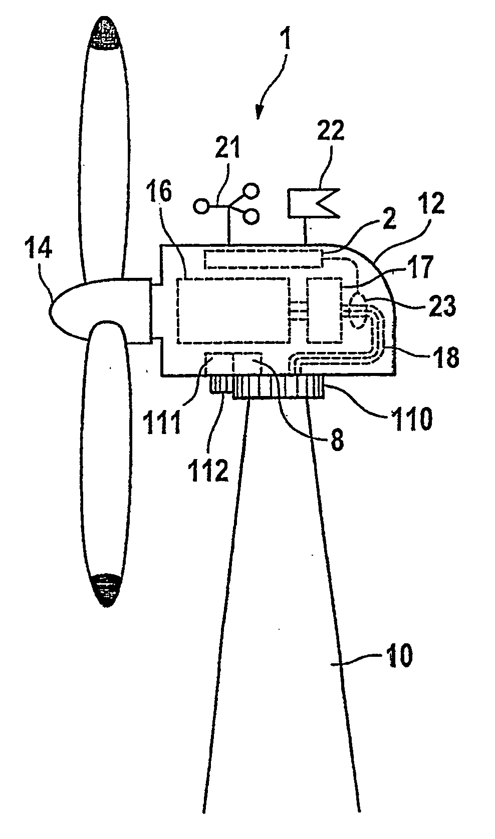
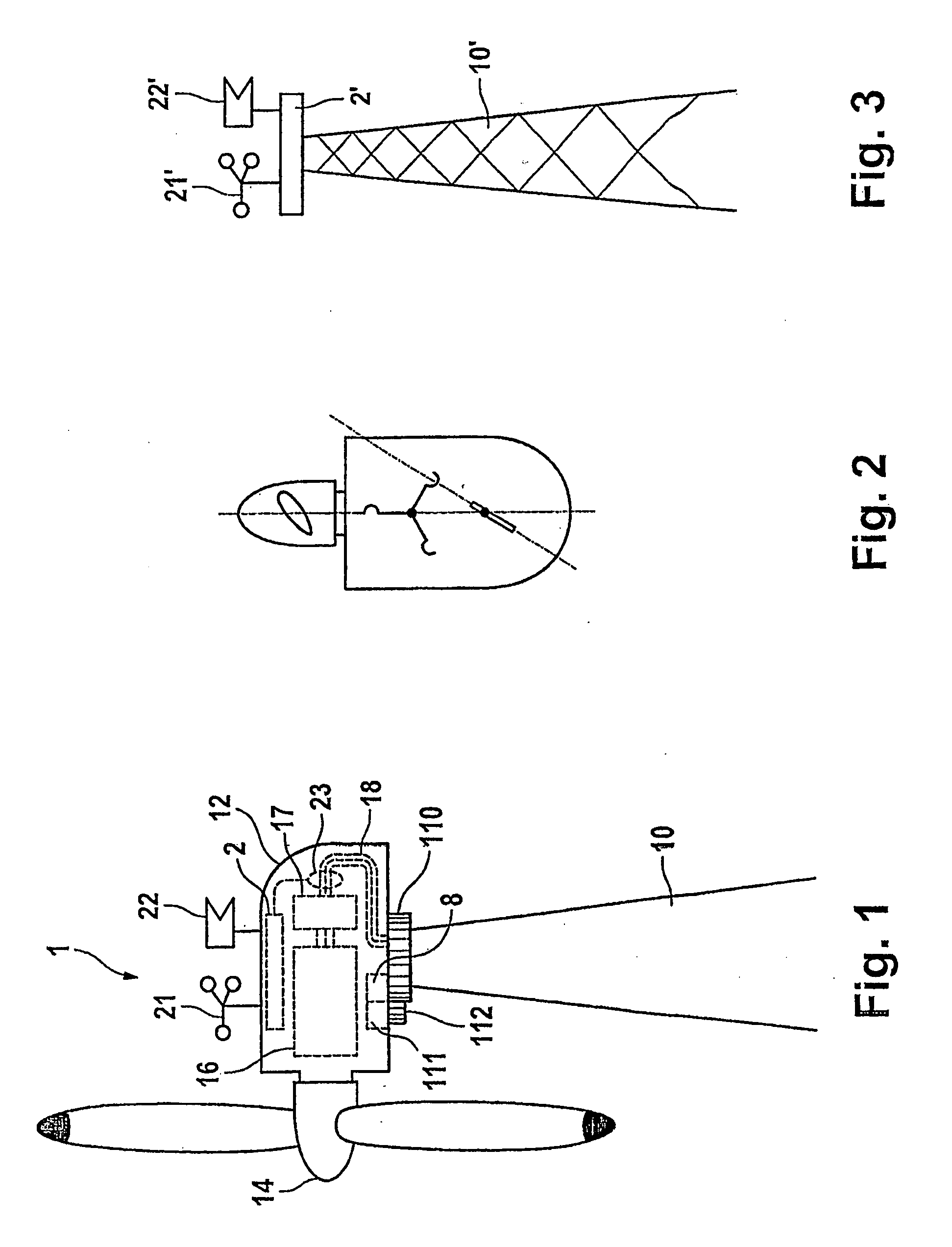
measurement device is preferably arranged on the machine housing. This has the
advantage of a compact and simple arrangement in the vicinity of the corresponding rotor. However, it is quite possible for the
measurement device to be arranged separately, for example on a separately installed measurement
tower. This variant is particularly appropriate when a plurality of wind energy installations have to be supplied with data from the same measurement device. An indirect
wind measurement can also be provided instead of a direct
wind measurement as described above. For example, the measurement devices can be designed to
record tower bending or rotor-blade bending torques. The latter offers the
advantage that it allows a relative measurement, in contrast to the measurement methods mentioned above, which measure the
wind strength in an absolute form (using Beaufort, meters per second, knots, etc.). Relative means that the rotor blade bending torques increase particularly markedly when the machine housing is not aligned correctly with the wind. This applies in particular to periodic changes in the rotor-blade bending torques.

