Multilayer electronic circuit device

a multi-layer electronic circuit and control device technology, applied in the direction of cross-talk/noise/interference reduction, electrical apparatus contruction details, association of printed circuit non-printed electric components, etc., can solve the problem of compactness of the electronic control device itself, and achieve excellent workability and accurate positioning

Inactive Publication Date: 2008-05-06
DENSO CORP
View PDF4 Cites 20 Cited by
  • Summary
  • Abstract
  • Description
  • Claims
  • Application Information

AI Technical Summary

Benefits of technology

[0009]According to the present invention, the multilayered flexible substrate is folded at the flexible portions so as to form a multilayered arrangement of the rigid substrate portions (equipped with the card edge connectors at their edges). The connector arrangement is simple. The number of parts is small. The cost is low.
[0077]As shown in FIG. 24, the entire body of the casing is integrally formed, for example, with a resin material. The number of parts is small. The workability in the assembling operation can be improved.

Problems solved by technology

Furthermore, the electronic control device itself is compact.

Method used


Image

  • Multilayer electronic circuit device
  • Multilayer electronic circuit device
  • Multilayer electronic circuit device

Examples


first embodiment

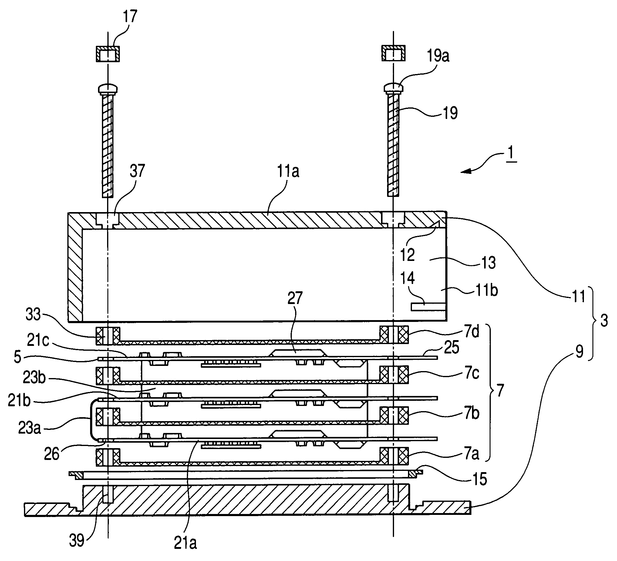
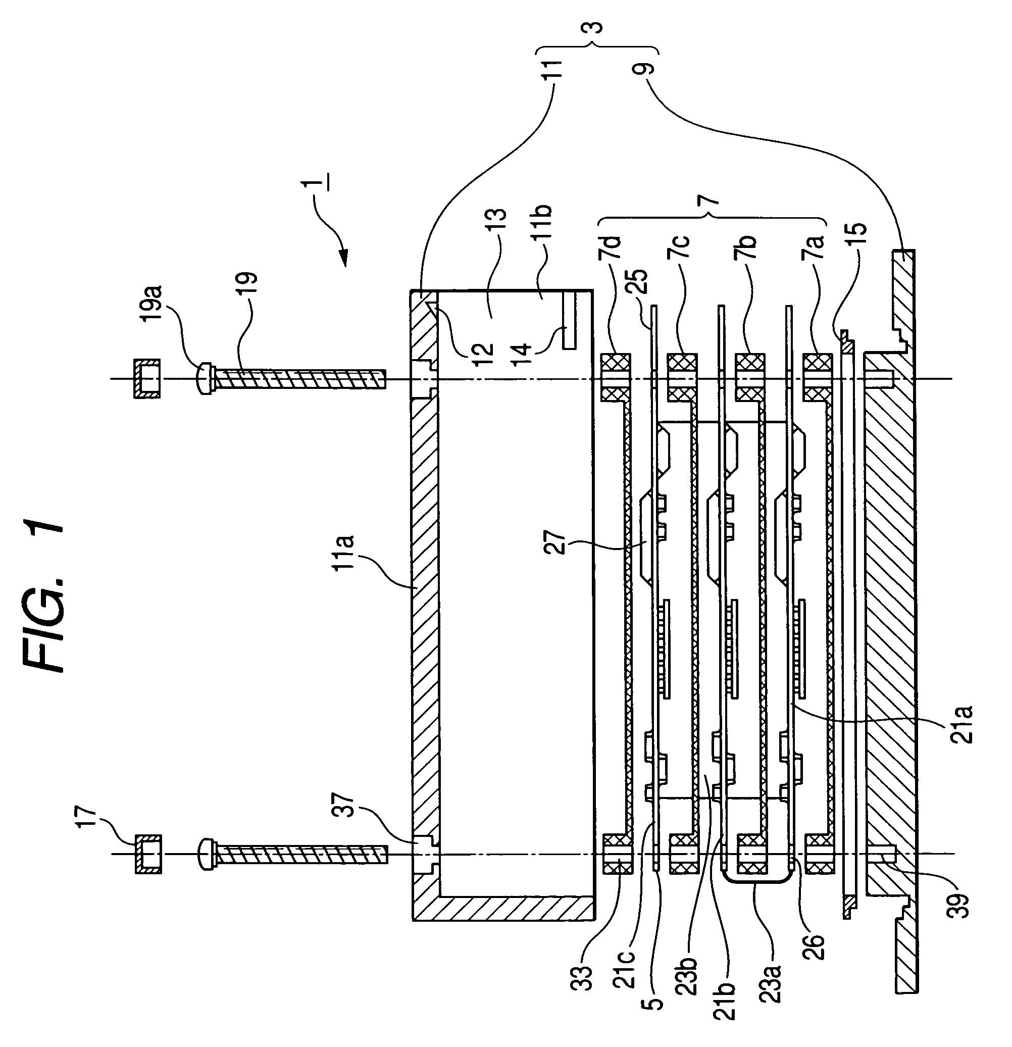
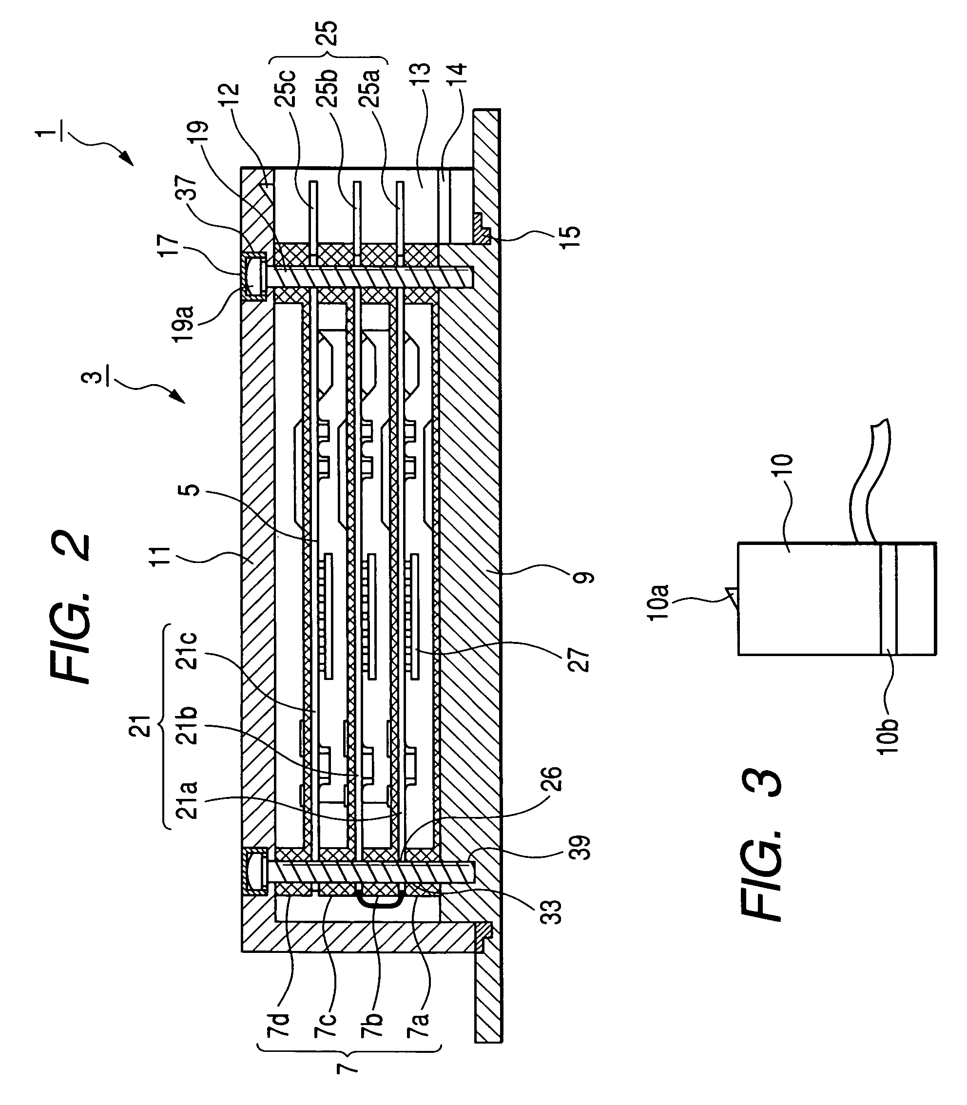
[0108]a) First of all, the arrangement of an electronic control device of a first embodiment will be explained. FIG. 1 is a front cross-sectional view showing an exploded state of an electronic control device in accordance with the first embodiment. FIG. 2 is a front cross-sectional view showing an assembled condition of the electronic control device in accordance with the first embodiment.

[0109]As shown in FIGS. 1 and 2, an electronic control device 1 includes a casing 3 configured into a rectangular parallelepiped. A multilayered flexible substrate 5 and a plurality of spacer 7a, 7b, 7c, and 7d (collectively referred to as spacer 7, hereinafter) are disposed in the casing 3.

[0110]The casing 3 includes a resin-made (or metallic) plate base 9 and a resin-made (or metallic) boxlike cover 11. The cover 11 is coupled with the plate base 9 from the upper surface side of the plate base 9. The casing 3 has a case opening 13 at one side surface (i.e. at the right side in the drawing). An e...

second embodiment

[0135]Next, a second embodiment of the present invention will be explained, although some of the disclosure of the second embodiment is identical with those of the first embodiment and will not be explained again.

[0136]a) First, the arrangement of an electronic control device in accordance with the second embodiment will be explained. FIG. 8 is a front cross-sectional view showing an exploded state of the electronic control device in accordance with the second embodiment.

[0137]As shown in FIG. 8, an electronic control device 61 includes a casing 67 consisting of a base 63 and a cover 65. A multilayered flexible substrate 69 and a pair of spacers 71a and 71b (collectively referred to as spacers 71, hereinafter) are disposed in the casing 67.

[0138]According to this embodiment, the multilayered flexible substrate 69 is folded at flexible portions 70a and 70b (collectively referred to as flexible portions 70, hereinafter) so that first to third rigid substrate portions 73a, 73b, and 73c...

third embodiment

[0149]Next, a third embodiment of the present invention will be explained, although some of the disclosure of the third embodiment is identical with those of the first embodiment and will not be explained again. As shown in FIG. 10, an electronic control device 91 of this embodiment includes a casing 97 consisting of a base 93 and a cover 95. A multilayered flexible substrate 99 and metallic spacers 101a, 101b, and 101c (collectively referred to as spacers 101, hereinafter) are disposed in the casing 97.

[0150]According to this embodiment, the multilayered flexible substrate 99 is folded at flexible portions 100a and 100b (collectively referred to as flexible portions 100, hereinafter) so that respective rigid substrate portions 103 and their card edge connectors 104 are disposed so as to form a multilayered arrangement.

[0151]According to the multilayered flexible substrate 99 of this embodiment, electronic components 109 are mounted on only upper surfaces of respective rigid substra...


PUM


Abstract

An electronic control device includes a multilayered flexible substrate and first to fourth spacers disposed in a casing. The multilayered flexible substrate, including first to third rigid substrate portions, is folded in a multilayered arrangement in such a manner that each rigid substrate portion is sandwiched between two spacers. The first rigid substrate portion is disposed at the lowest position to arrange a lowermost layer. The second rigid substrate portion is folded upward relative to the first flexible portion by 180 degrees to arrange an intermediate layer. The third rigid substrate portion is folded upward relative to the second flexible portion by 180 degrees to arrange an uppermost layer. The card edge connectors are laminated or layered with predetermined gaps and positioned in a case opening.

Description

CROSS-REFERENCE TO RELATED APPLICATION[0001]This application is based upon and claims the benefit of priority from earlier Japanese Patent Application No. 2004-7238 filed on Jan. 14, 2004 and the Japanese Patent Application No. 2004-315777 filed on Oct. 29, 2004 so that the descriptions of which are incorporated herein by reference.BACKGROUND OF THE INVENTION[0002]The present invention relates to an electronic control device having a casing accommodating a circuit substrate used for the control of an automotive vehicle or the like.[0003]FIG. 25 shows a conventional electronic control device installed in an automotive vehicle or the like for various controls (refer to the Japanese Patent Application Laid-open No. 2003-229678). This electronic control device P1 includes electronic components P2 and a heat sink P3 mounted on a circuit substrate P4 which are housed in a casing P5. A connector P6, as a separate member, is attached to the edge of the circuit substrate P4.[0004]However, ac...

Claims


Application Information

Patent Timeline
Patent Type & Authority Patents(United States)
IPC IPC(8): H01R12/16H05K9/00H02G3/16H05H7/14H05K1/02H05K1/18H05K7/02H05K7/14H05K7/20
CPCH05K1/189H05K7/023H05K1/0218H05K2201/2036
Inventor KOJIMA, AKIYOSHI
Owner DENSO CORP
Why Eureka
Try Eureka