Adjacent interference removal device

a technology of interference removal and adjacent, which is applied in the direction of electrical equipment, radio transmission, transmission, etc., can solve the problems of deteriorating reception quality due to adjacent, and difficult to improve an actual reception quality

Inactive Publication Date: 2008-05-06
PIONEER CORP
View PDF19 Cites 14 Cited by
  • Summary
  • Abstract
  • Description
  • Claims
  • Application Information

AI Technical Summary

Benefits of technology

[0013]The present invention has been accomplished in order to solve the aforementioned conventional problem, and it is an object of the present invention to provide an adjacent inference removal device capable of improving an actual reception quality.
[0016]The adjacent interference removal device of the present invention further comprises: a third narrow band filter which inputs into itself the IF signal, uses said carrier frequency as its center, and has a pass frequency band width narrower than that of each of the first and second narrow band filters; and third detecting means for detecting a third signal having passed through the third narrow band filter, and supplying a third detection signal to the signal selecting means. Once the identifying means identifies that an interference signal is contained in each of the first signal and the second signal, the control means allows the signal selecting means to output the third detection signal.

Problems solved by technology

Generally, with regard to an FM broadcasting receiver or the like, if an interference signal from an adjacent broadcasting station has been generated adjacent to a received signal from a desired broadcasting station, a sort of reception quality deterioration will occur due to the adjacent interference.
However, although it is possible to remove the influence of an interference signal upon limiting the band of each IF signal within 50 KHz by virtue of the second IF filter (10), since a distortion occurs in a detection output signal outputted from the detecting circuit (6), it has been found difficult to improve an actual reception quality.
However, since a distortion occurs in a detection output signal outputted from the detecting circuit (6), it has been found difficult to improve an actual reception quality.

Method used


Image

  • Adjacent interference removal device
  • Adjacent interference removal device
  • Adjacent interference removal device

Examples


embodiment

Detailed Embodiment

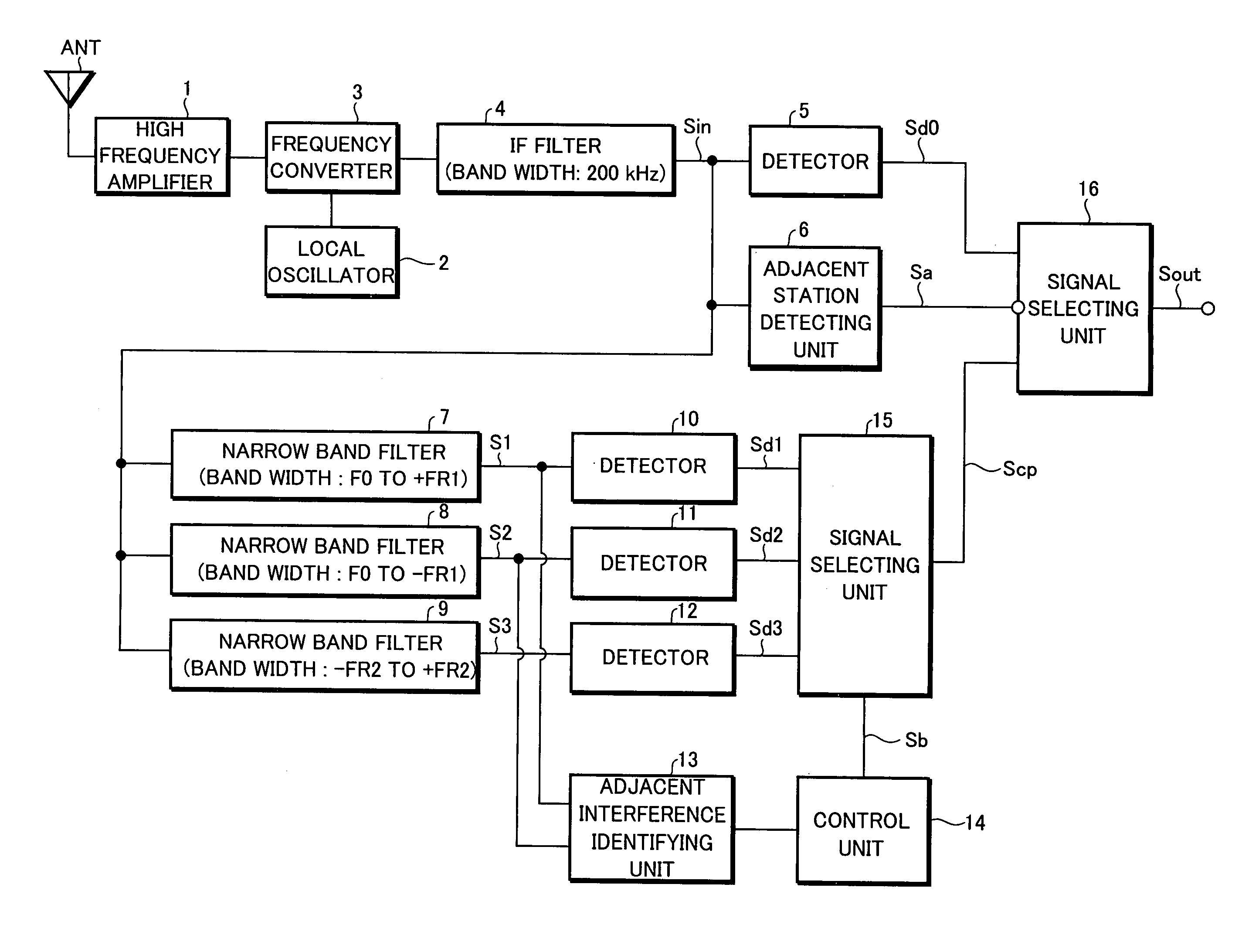
[0074]A detailed embodiment according to the present invention will be described below with reference to FIGS. 3 through 12. FIG. 3 and FIG. 4 are block diagrams showing the structure of an adjacent interference removal device formed according to the present embodiment. However, elements which are the same as or corresponding to those shown in FIG. 1 will be represented by the same reference numerals.

[0075]The structure of an adjacent interference removal device according to the present embodiment shown in FIG. 3 and FIG. 4 will be described in comparison with the embodiment shown in FIG. 1. In fact, the signal selecting unit 15 shown in FIG. 1 is formed by switching circuits 15a and 15b shown in FIG. 3, while the signal selecting unit 16 shown in FIG. 1 is formed by a switching circuit 16 shown in FIG. 3. Practically, these switching circuits 15a, 15b, and 16 are formed by for example two-input one-output type analog switches or the like.

[0076]Further, an adjacen...


PUM


Abstract

An adjacent interference removal device capable of providing an improved reception quality. An IF signal Sin having passed through an IF filter having a pass frequency band width of 200 kHz is supplied to a first narrow band filter having a pass frequency band width extending from a center frequency (carrier frequency) of the IF filter to +50 kHz, as well as to a second narrow band filter having a pass frequency band width extending from a center frequency (carrier frequency) of the IF filter to −50 kHz. When an interference signal is contained in a first signal S1 outputted from the first narrow band filter but not in a second signal S2 outputted from the second narrow band filter, and when an interference signal is contained in a detection signal Sd2 generated by detecting the second signal S2 in a detector and contained in the second signal S2 itself but not contained in the first signal S1, the detection signal Sd1 generated by detecting the first signal S1 in another detector is outputted by performing a switchover in a signal selecting unit.

Description

BACKGROUND OF THE INVENTION[0001]The present invention relates to an adjacent interference removal device for removing an influence of an interference signal caused by an adjacent interference, from a received signal received by an FM broadcasting receiver or the like.[0002]The present application claims priority from Japanese Applications No. 2004-19710, the disclosures of which are incorporated herein by reference.[0003]Generally, with regard to an FM broadcasting receiver or the like, if an interference signal from an adjacent broadcasting station has been generated adjacent to a received signal from a desired broadcasting station, a sort of reception quality deterioration will occur due to the adjacent interference.[0004]Conventionally, when such an adjacent interference has occurred, an applicable method is to reduce, on the receiver side, the pass band width of an IF filter which passes an intermediate frequency signal (IF signal), thereby removing the influence of the interfe...

Claims


Application Information

Patent Timeline
Patent Type & Authority Patents(United States)
IPC IPC(8): H04B1/10H04B1/16H04B1/18
CPCH04B1/1036H04B1/109H04B2001/1045
Inventor SUGANUMA, HISASHI
Owner PIONEER CORP
Why Eureka
Try Eureka