Key unit

a key and key holder technology, applied in the field of key units, can solve the problems of increasing the thickness of the grip case and the inability to carry keys, and achieve the effect of facilitating assembly and enhancing assembly strength

a key and key holder technology, applied in the field of key units, can solve the problems of increasing the thickness of the grip case and the inability to carry keys, and achieve the effect of facilitating assembly and enhancing assembly strength

US7370501B2Active Publication Date: 2008-05-13HONDA LOCK MFG CO LTD

Image

  • Key unit
  • Key unit
  • Key unit

Examples


Embodiment Construction

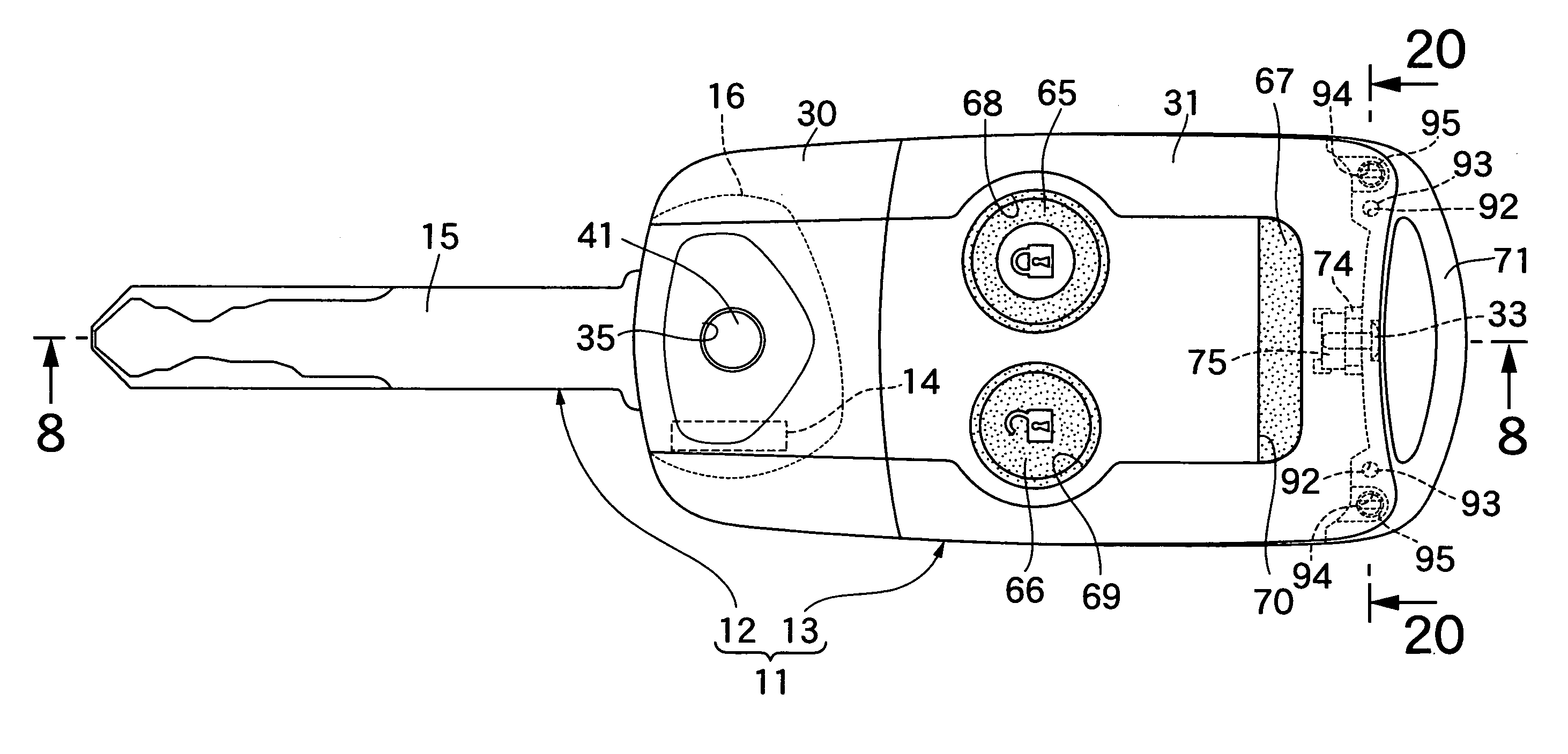
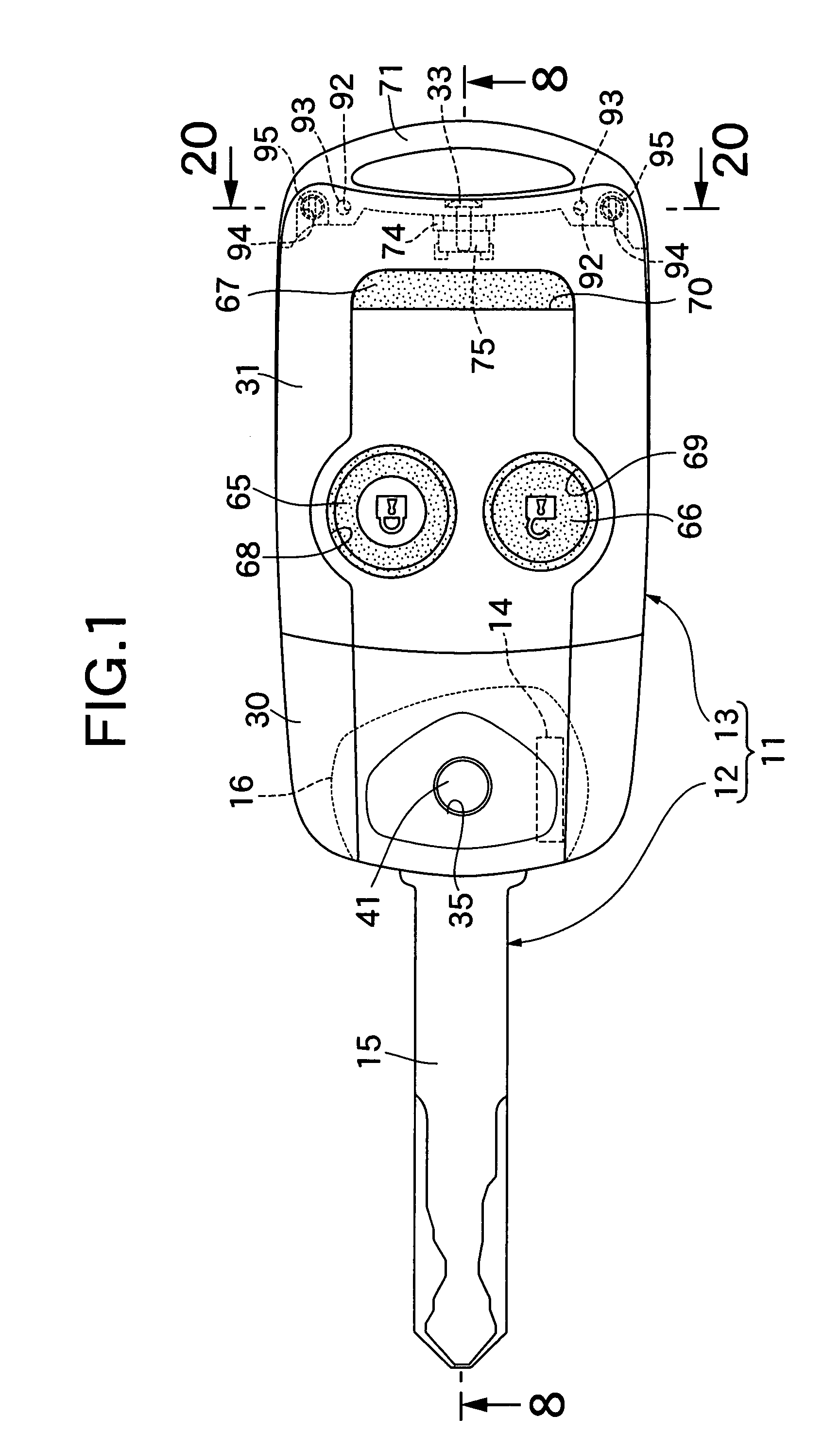
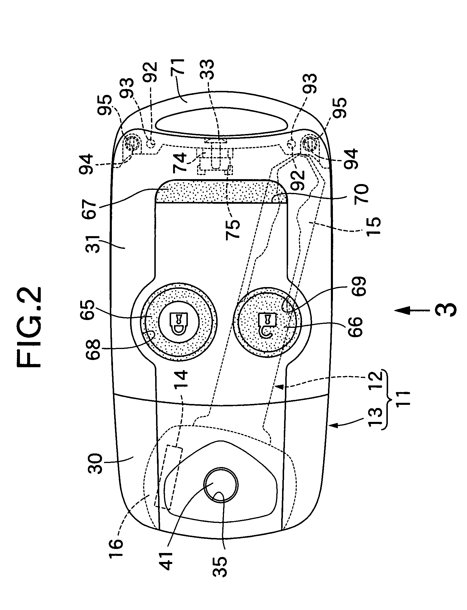
[0035]Referring first to FIG. 1 to FIG. 3, a key unit 11 comprises a mechanical key 12, and a grip case 13 supporting the mechanical key 12 so that the mechanical key 12 can pivot between a retracted position in which the entire mechanical key 12 is retracted and a projecting position in which part of the mechanical key 12 projects.

[0036]In FIG. 4 and FIG. 5, the mechanical key 12 comprises a metal key plate 15 and a key head 16 joined to one end of the key plate 15. The key head 16 is formed from a synthetic resin such that one end of the key plate 15 is insert-bonded thereto. Further, the key head 16 includes a rectangular housing recess 17 extending parallel to the longitudinal direction of the key plate 15 so as to open on one side face of the key head 16. Furthermore, the key head 16 includes recesses 19 and 19 communicating with opposite ends of the housing recess 17 in the longitudinal direction thereof and at one end in the width direction, the recesses 19 and 19 being shall...


PUM


Abstract

A key unit includes a grip case which includes at least a pair of synthetic resin case members joined to each other, and a mechanical key supported in the grip case and having a pivotable key head. A plurality of fitting projections are projectingly provided integrally on a metal holder ring held between the case members. The fitting projections are respectively fitted into a plurality of fitting holes provided in at least one of the case members. An engagement hook resiliently engaging with an engagement hole provided in the holder ring is projectingly provided integrally on one of the case members. This facilitates assembling and enhances assembly strength in attaching the metal holder ring to the grip case.

Description

RELATED APPLICATION DATA[0001]The present invention is based upon Japanese priority application Nos. 2006-79330, 2006-79331 and 2006-79332, which are hereby incorporated in their entirety herein by reference.BACKGROUND OF THE INVENTION[0002]1. Field of the Invention[0003]The present invention relates to a key unit comprising: a grip case which includes at least a pair of synthetic resin case members joined to each other; and a mechanical key which is supported in the grip case and which includes a key plate capable of being inserted into a cylinder lock and a key head joined to one end of the key plate; the mechanical key being capable of pivoting the mechanical key between a retracted position in which the entire mechanical key is retracted and a projecting position in which the key plate projects.[0004]2. Description of Related Art[0005]Such a key unit is already known from, for example, Japanese Patent Application Laid-open No. 63-110377, in which a key head of a mechanical key i...

Claims


Application Information

Patent Timeline
13 May 2008
Publication
US7370501B2
IPC
E05B19/00
CPC
E05B19/043; G07C9/00944; Y10T70/7802; Y10T70/7876; Y10T70/8757
Inventors
MIYATA, KAZUHIRO; KAWASE, MIKIHIKO