Flat belt durability tester

a durability tester and belt technology, applied in the direction of elastic gauge deformation force measurement, instrument, force measurement by force/torque/work, etc., can solve the problems of center belt trapped between vertical support structures that cannot be easily disassembled, limit on one belt, etc., and achieve the effect of accelerating wear conditions

Inactive Publication Date: 2008-05-13
BLUE LEAF I P INC
View PDF13 Cites 2 Cited by
  • Summary
  • Abstract
  • Description
  • Claims
  • Application Information

AI Technical Summary

Benefits of technology

[0008]An additional feature of the machine is that it includes both “inside-wrap” pulleys that contact the belt surface that usually contacts pulleys and “outside-wrap” pulleys that can be placed in contact with the outside of the belts to add wear and shear stress to that side of the belts and better simulate field conditions.
[0009]The present invention can thereby simulate and even accelerate the wear conditions on flat belts used in various applications, and it provides significant information to predict belt performance under field conditions.

Problems solved by technology

The limitation on the one belt exists because the three belts are positioned side by side.
Thus, while the outer two belts are essentially supported by cantilevered pulleys that permit easy belt installation and removal, the center belt is trapped between vertical support structures that can not be easily disassembled.
However, if a belt travels too far sideways on a guide pulley, the movement is sensed by a photocell sensor, and the test machine is shutdown.

Method used


Image

  • Flat belt durability tester
  • Flat belt durability tester
  • Flat belt durability tester

Examples


Embodiment Construction

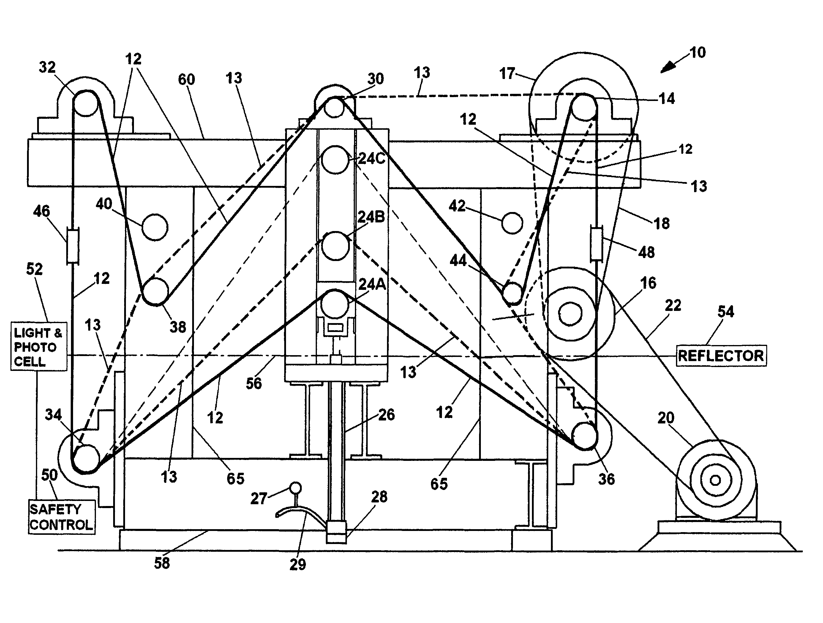
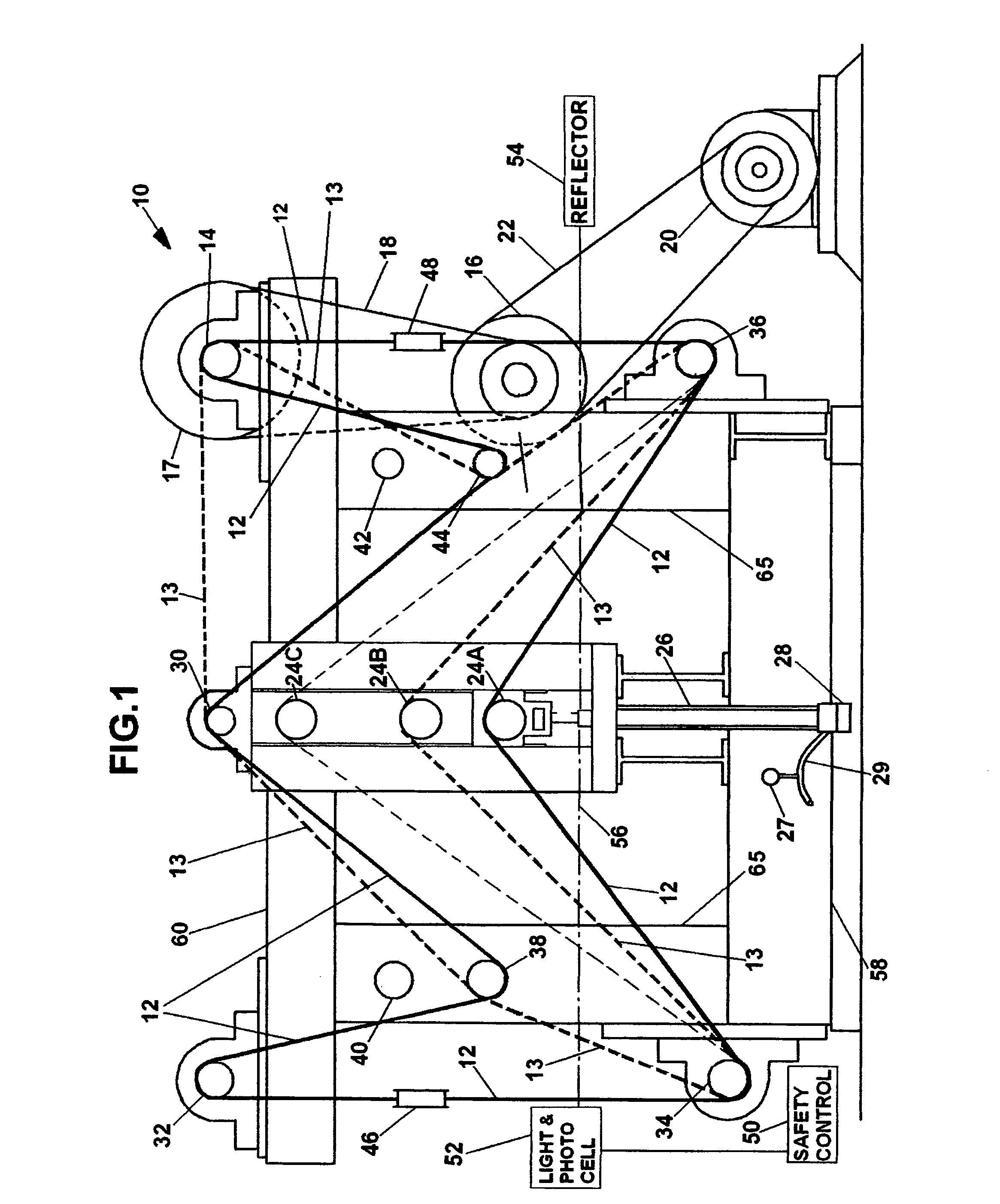
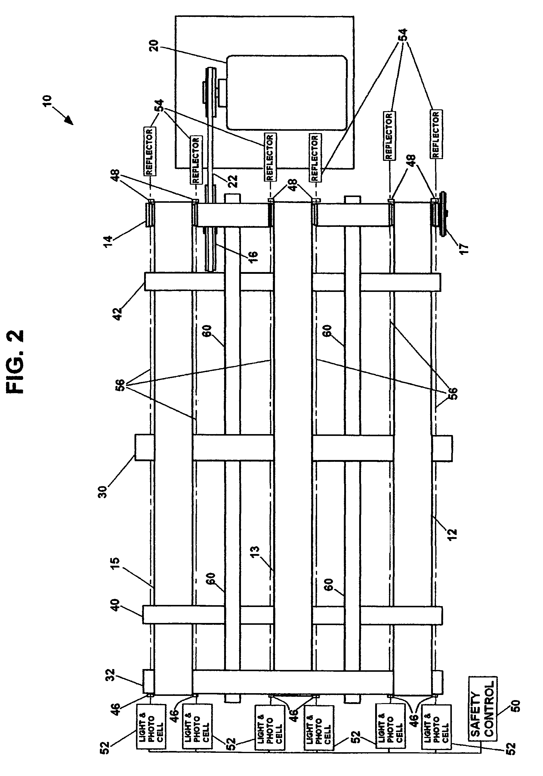
[0013]FIG. 1 is a schematic side view of flat belt tester 10 of the preferred embodiment of the invention, and FIG. 2 is a schematic top view of belt tester 10 of the preferred embodiment of the invention. Only a limited part of the support structure of tester 10 is shown in FIGS. 1 and 2 in order to more clearly show the locations and orientations of the various pulleys and the belts being tested. Furthermore, since FIG. 1 is a side view only a single belt 12 would normally be seen in that view. FIG. 2, which is a schematic top view of tester 10, shows the location of all three belts that can be tested simultaneously. As is also more clearly shown in FIG. 2, most of the pulleys whose ends are shown in FIG. 1 extend for the entire width of tester 10 and can, but most need not always, be used for all the belts being tested.

[0014]FIG. 1 also shows the manner in which belts of two different sizes can be tested. Belt 12, indicated as a dark solid line, shows the path of a 420 inch belt ...


PUM

PropertyMeasurementUnit
lengthsaaaaaaaaaa
hydraulic pressureaaaaaaaaaa
tensionaaaaaaaaaa

Abstract

The apparatus is a multi-speed flat belt durability tester that can simultaneously test several belts of different lengths. The tester can apply different tensions to each belt with a tension pulley powered by a hydraulic cylinder, and it monitors the tracking of the belts with photocell sensors. At least two belt test positions located at the outer edges of the apparatus include cantilevered pulley ends that greatly facilitate installation and removal of the belts being tested.

Description

BACKGROUND OF THE INVENTION[0001]This invention deals generally with an apparatus for testing power transmission belts and more specifically for a machine for life testing of flat belts of substantially different lengths.[0002]Numerous power transmission belts are used on farm machinery, and there can even be six to eight belts on a single machine. Although such belts are usually thin flat belts, they can be either true “endless” belts or so called “laced” belts, those that have a spliced junction forming the loop. Field test evaluation of the performance of such belts under normal operation in crop conditions can take years. Furthermore, because of the width of such belts, which are up to a foot wide, the pulleys they ride upon are typically supported at both ends, making installation and removal of such belts very cumbersome and time consuming.[0003]Several belt testing machines are patented, but all such devices have some shortcomings. For one thing most are designed for the comm...

Claims


Application Information

Patent Timeline
Patent Type & Authority Patents(United States)
IPC IPC(8): G01L1/04
CPCG01M13/023
Inventor STAUFFER, DAVID B.KORLINCHAK, GEORGE
Owner BLUE LEAF I P INC
Why Eureka
Try Eureka