Reflective arrowhead traffic sign apparatus with magnetic mounting

a traffic sign and magnetic mounting technology, applied in traffic signals, instruments, roads, etc., can solve the problem that the arrow wings cannot be formed into two separate sets of arrow wings on the opposite end of the horizontal shaft, and achieve the effect of high reflective, easy assembly and mounting, and high reflective

Inactive Publication Date: 2008-05-13
ZACAABEL
View PDF74 Cites 19 Cited by
  • Summary
  • Abstract
  • Description
  • Claims
  • Application Information

AI Technical Summary

Benefits of technology

[0012]Accordingly, it is an advantage of the present invention to provide a highly reflective arrowhead traffic sign that can be easily assembled and mounted on the side or body of a vehicle, or that can be “hung” from traffic cones in a raised or elevated position.
[0013]It is another advantage of the present invention to provide a highly reflective arrowhead sign structure that can be assembled in more than one length while still being structurally rigid, and thus able to “stand” upright by use of certain mounting points.
[0014]It is a further advantage of the present invention to provide a highly reflective arrowhead traffic sign that telescopes for ease of assembly and use, but is still structurally rigid and able to stand upright by use of certain mounting points.
[0015]It is yet a further advantage of the present invention to provide a highly reflective arrowhead traffic sign in which the main members are constructed by an extrusion process to keep the cost low, while providing a telescoping set of horizontal members and at least one wing set of arrowhead members that pivot along one of the horizontal members.
[0016]It is yet another advantage of the present invention to provide a highly reflective arrowhead sign structure that exhibits two pivotable wing sets that are mounted to the two horizontal ends of a main member, in which the individual members of the wing sets can be adjusted to any angle desired by a user, so that both wing sets can be pointed in the same direction, or in opposite directions, if desired.
[0017]It is still another advantage of the present invention to provide a highly reflective arrowhead sign structure that has pivotable wing members that extend beyond the outer borders of a horizontal main member, in which each of the main structural members can be extruded to keep the cost low, and in which each of the main members exhibits a planar surface for attachment of a highly reflective or retroreflective material.

Problems solved by technology

However, Magliocco could not be formed into two separate sets of arrow wings on opposite ends of the horizontal shaft, because its left end is attached to a vertical post that itself is mounted to the ground.

Method used


Image

  • Reflective arrowhead traffic sign apparatus with magnetic mounting
  • Reflective arrowhead traffic sign apparatus with magnetic mounting
  • Reflective arrowhead traffic sign apparatus with magnetic mounting

Examples


second embodiment

[0099]the reflective arrowhead sign according to the present invention will now be described, beginning with FIG. 8. FIG. 8 illustrates a longitudinal member from one of its ends, in which the member itself is generally designated by the reference numeral 160. Longitudinal member 160 exhibits a substantially planar upper surface 162, and includes two longitudinal edges that border the planar surface 162, which are shaped as mainly circular formations at 164 and 166. These circular (or arcuate) edges 164 and 166 will retain an interior member that is placed within the spaces illustrated at 169. Each of these arcuate or circular edges 164 and 166 is made into a semi-circular shape of a sort, and they terminate at end points (or edges) 165 and 167, respectively.

[0100]The longitudinal element 160 also is provided with a number of openings or through-holes 168, which are placed in both of the arcuate longitudinal edges 164 and 166. These openings 168 will be more easily seen in other vie...

embodiment 200

[0113]Referring now to FIG. 13, the reflective arrowhead sign 200 is illustrated in the extended telescoping position. As seen in FIG. 13, the slidable members 170 and 180 are extended out from the open end of the largest longitudinal member 160. This exposes the substantially planar surfaces 172 and 182 of these telescoping members 170 and 180. As discussed above, the planar surfaces 172 and 182 are designed so that a highly reflective or retroreflective tape or sheeting material can be placed thereon. This will provide a different overall shape to the arrowhead design of this embodiment 200 of the present invention. Of course, the wing members 210 and 240 could be located at different positions along the horizontal (as viewed in FIG. 13) line or longitudinal axis of the telescoping members 160, 170, and 180, all without departing from the principles of the present invention.

[0114]The arrowhead wing sets 210 and 240 can be pivoted to any position desired by the user, and can be piv...

embodiment 400

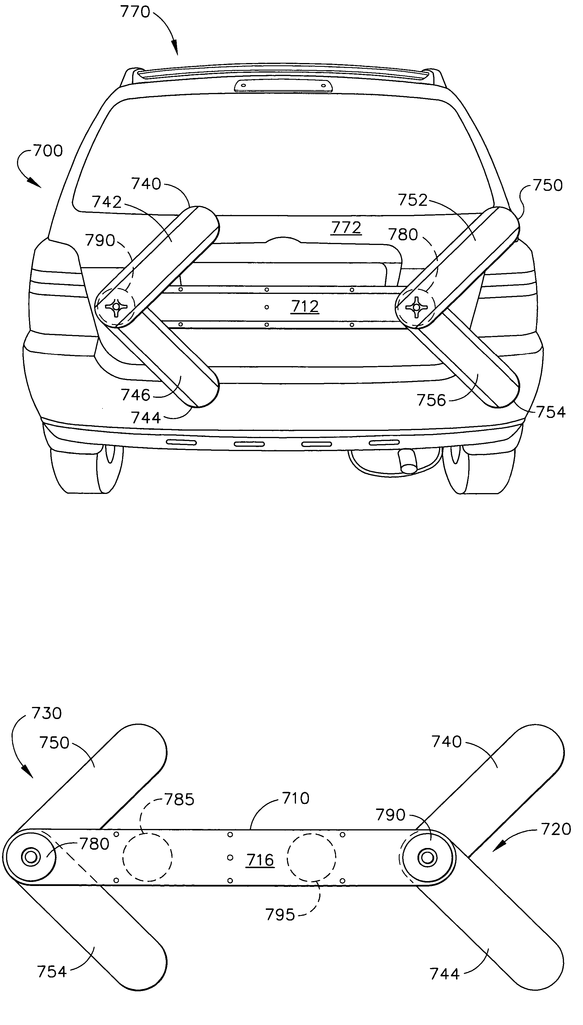
[0125]Each of the wing sets 420 and 430 are pivotable about a pivot point, as noted above. In this alternative embodiment 400, the pivot point is composed of an opening in the main member 410, and a pivot pin and thumbscrew combination, in which the thumbscrew is visible in FIG. 19 at 422 and 432 for the wing sets 420 and 430, respectively. It will be understood that the actual angular position of the individual wings 440, 444, 450, and 454 can be determined by the user, who first loosens the thumbscrews 422 and 432, and then moves in a rotatable manner the individual wings of the wing sets 420 and 430. Once the wing sets are adjusted so that their members 440, 444, 450, and 454 are positioned in the desired locations, then the thumbscrews 422 and 432 can be re-tightened to hold the wing sets 420 and 430 in their desired placement.

[0126]The main member 410 also has a substantially planar surface at 412 for placement or attachment of highly reflective or retroreflective tape or sheet...


PUM


Abstract

A highly reflective arrowhead traffic sign is provided which exhibits an arrow shape to “aim” traffic away from a lane. A horizontal longitudinal member has at least one pair of arrow-shaped “wings” that extend beyond the outer boundary of the horizontal member. The wing sets can be attached to the horizontal member by use of locating holes and mating pins, or they can be pivotally mounted on the horizontal member. The arrow wings can be shaped into a configuration that points to the left or to the right, or simultaneously point to both the left and right, thereby indicating to traffic that a lane is closed, and that traffic must go either left or right to avoid the closed lane. The signs can be mounted in different ways, using hooks with suction cups or traffic cones, or using built-in magnets.

Description

CROSS-REFERENCE TO RELATED APPLICATIONS[0001]The present application is a continuation-in-part to application Ser. No. 10 / 464,172, titled “Reflective Arrowhead Traffic Sign Apparatus,” filed on Jun. 18, 2003 now U.S. Pat. No. 6,948,446.TECHNICAL FIELD[0002]The present invention relates generally to traffic direction signs and is particularly directed to highly-reflective signs of the type which exhibit an arrow shape to “aim” traffic to one side or the other along a roadway. The invention is specifically disclosed as a horizontal longitudinal member that has at least one pair of arrow-shaped “wings” that extend beyond the outer boundary or perimeter of the horizontal member. The horizontal member can be of a single-piece construction, or it can be segmented into several pieces that are easily joined to form a single, longer member, or it can be of a telescoping design so as to be readily formed into a longer shape. The arrow wings can be attached to the horizontal member by use of l...

Claims


Application Information

Patent Timeline
Patent Type & Authority Patents(United States)
IPC IPC(8): E01F9/019E01F9/012E01F9/619E01F9/646E01F9/677G09F7/18
CPCB60Q7/005E01F9/0126E01F9/013E01F9/619E01F9/654E01F9/662E01F9/688
Inventor GREVES, KENNETH J.
Owner ZACAABEL
Why Eureka
Try Eureka