AI technical title is built by Patsnap AI team. It summarizes the technical point description of the patent document.
a power strip and seat technology, applied in the field of aircraft electronic systems, can solve the problems of increasing the complexity of the operation and the amount of time required to install seats, the process is cumbersome and time-consuming, and the process of rewiring an aircraft is costly and time-consuming
Inactive Publication Date: 2008-05-13
THE BOEING CO
View PDF10 Cites 39 Cited by
Summary
Abstract
Description
Claims
Application Information
AI Technical Summary
This helps you quickly interpret patents by identifying the three key elements:
Problems solved by technology
Method used
Benefits of technology
Benefits of technology
This solution simplifies the installation and reconfiguration of aircraft passenger seats by allowing power and data to be transmitted along a continuous bus, reducing installation time and costs associated with re-wiring.
Problems solved by technology
Taking care to avoid the exposed, wires increases both the complexity of the operation and the amount of time required to install the seats.
As would be expected, re-wiring an aircraft is a costly and time consuming process.
Method used
Image
Click on the blue label to locate the original text in one second.
Reading with bidirectional positioning of images and text.
Examples
Embodiment Construction
[0019]The following description of the preferred embodiments is merely exemplary in nature and is in no way intended to limit the invention, its application, or uses.
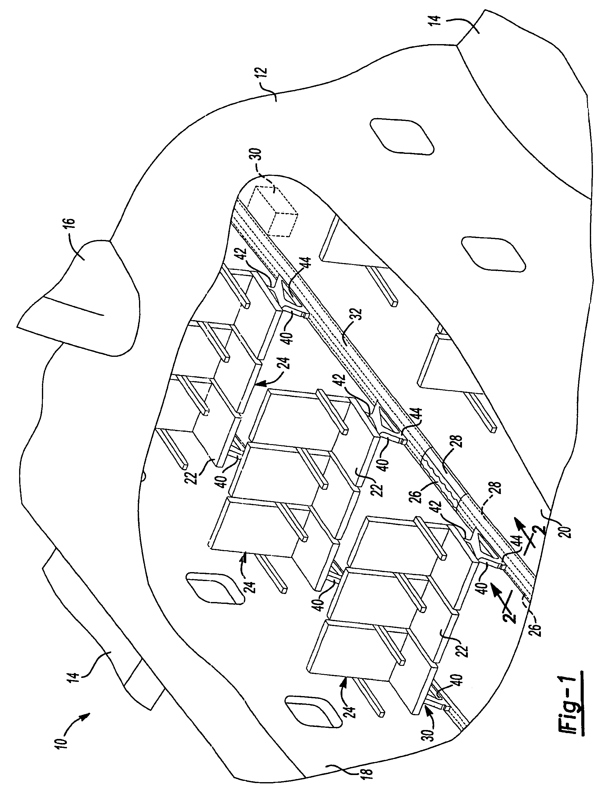
[0020]With initial reference to FIG. 1, a mobile platform in the form of a passenger aircraft equipped with a power distribution system according to the present invention is illustrated at reference numeral 10. It will be appreciated, however, that the present invention is not limited to use only in commercial aircraft and can be implemented in any form of mobile platform, such as a ship, train, bus, motor craft, etc.
[0021]The aircraft 10 generally includes a fuselage 12, wings 14, and a tail fin 16. The fuselage 12 includes a passenger cabin 18 having a floor 20. At the floor 20 are numerous passenger seats 22. Two or more passenger seats 22 are grouped together as a seat group 24. One or more seat tracks 26 extend along the floor 20 to secure the seat groups 24 into position. A power bus system 28 for delivering power...
PUM
Abstract
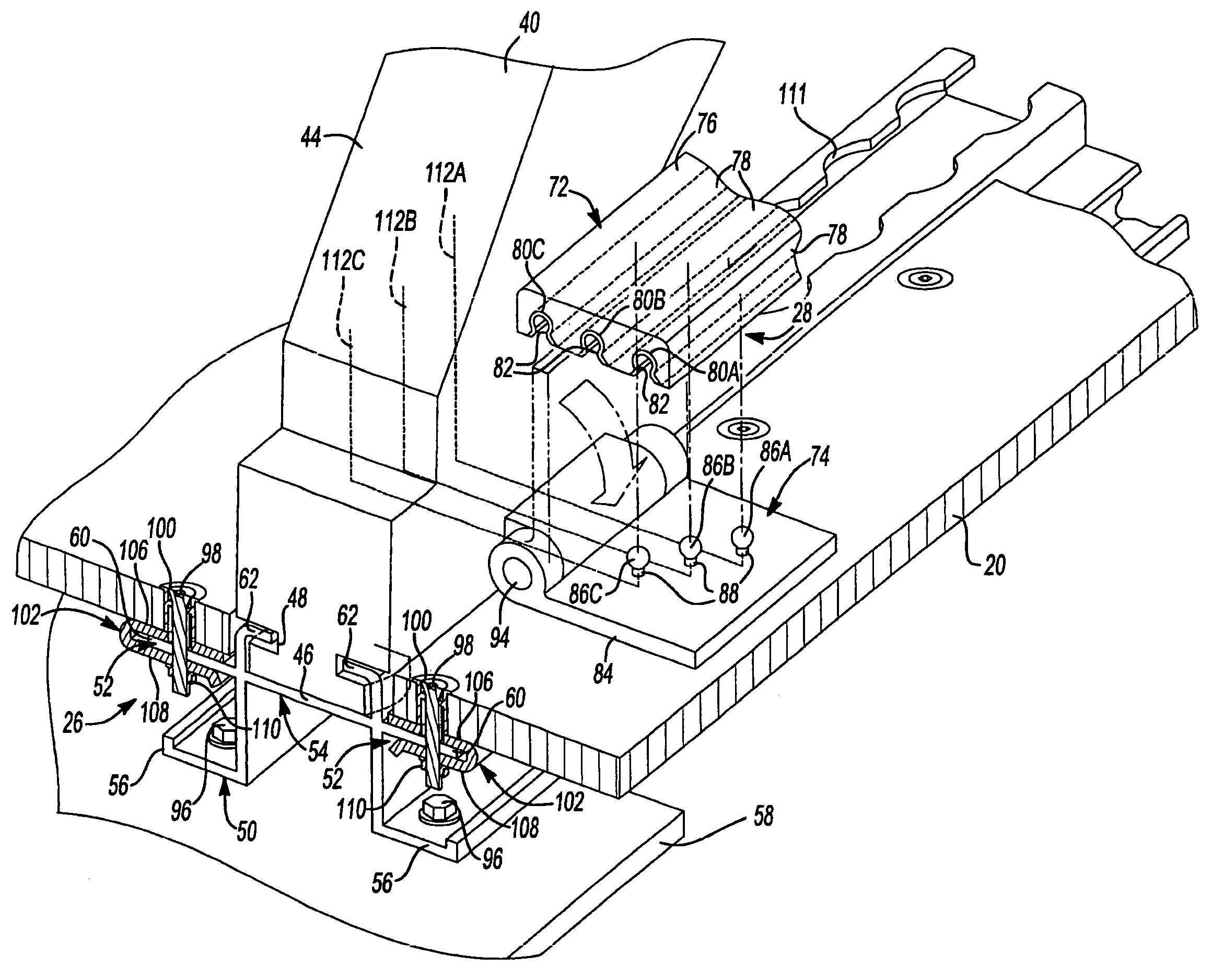
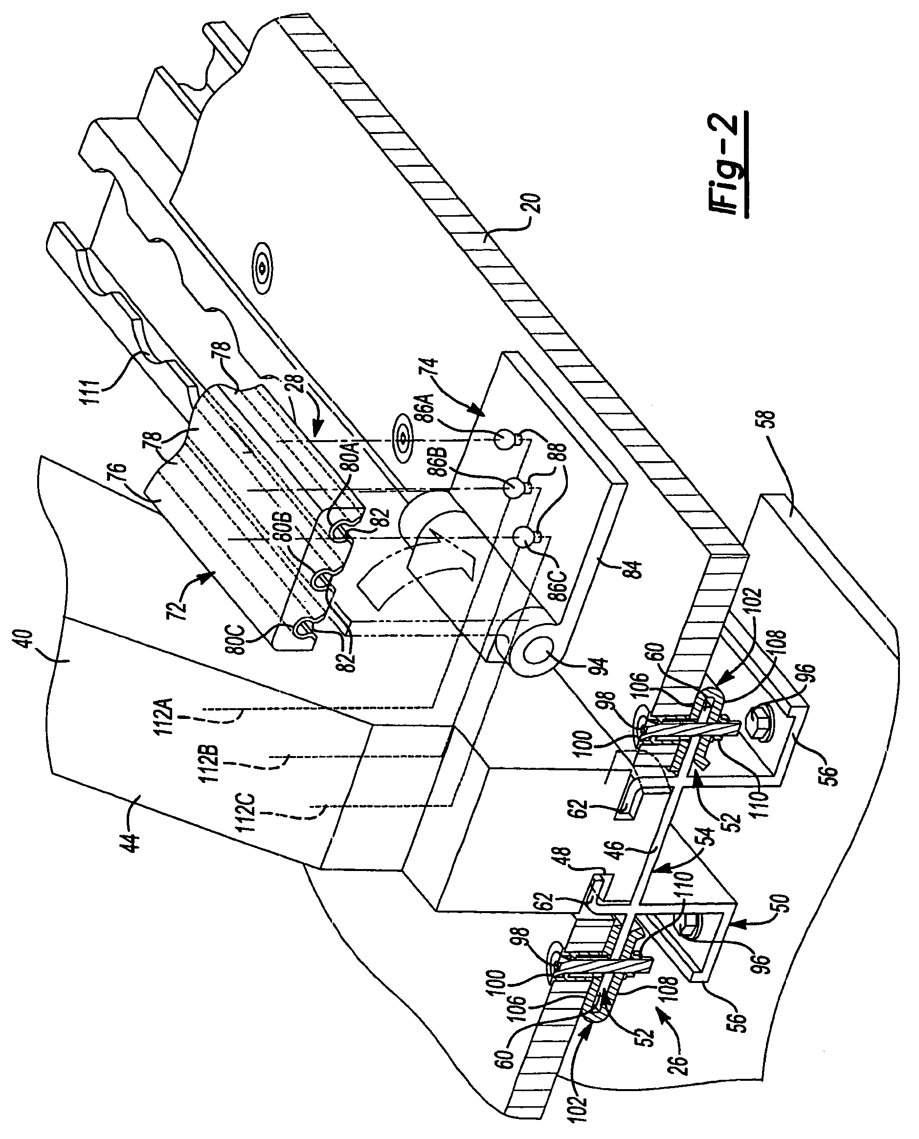
A system for distributing signals between a first seat and a second seat of a platform. The system generally includes an elongated bus and a connector operable to provide a connection between the bus and the passenger seats. Signals can be transmitted between the bus and the passenger seats, via the connector, at any point along the power bus, thus eliminating the need to run separate connections between the signal source and each seat. The bus is connected to the connector by depressing the bus upon the connector. This system and method significantly reduces the amount of time, energy, and expense necessary to individually wire each passenger seat to receive signals, such as power and / or data.
Description
CROSS-REFERENCE TO RELATED APPLICATIONS[0001]This application claims the benefit of U.S. provisional application Ser. No. 60 / 556,823 filed Mar. 27, 2004, which is incorporated herein by reference.[0002]The following applications are also incorporated by reference herein: provisional application Ser. No. 60 / 556,826 filed on Mar. 27, 2004; provisional application Ser. No. 60 / 557,044 filed on Mar. 27, 2004; provisional application Ser. No. 60 / 556,747 filed on Mar. 27, 2004; provisional application Ser. No. 60 / 556,748, filed on Mar. 27, 2004; U.S. application Ser. No. 10 / 810,324 filed on Mar. 27, 2004; U.S. utility application Ser. No. 10 / 898,729 filed on Jul. 23, 2004; U.S. utility application Ser. No. 10 / 936,004 filed on Sep. 8, 2004; U.S. utility application Ser. No. 10 / 983,906 filed on Nov. 8, 2004; U.S. utility application Ser. No. 10 / 943,035 filed on Sep. 16, 2004; and U.S. utility application Ser. No. 10 / 921,553 filed on Aug. 19, 2004.FIELD OF THE INVENTION[0003]The present inven...
Claims
Application Information
Patent Timeline
Application Date:The date an application was filed.
Publication Date:The date a patent or application was officially published.
First Publication Date:The earliest publication date of a patent with the same application number.
Issue Date:Publication date of the patent grant document.
PCT Entry Date:The Entry date of PCT National Phase.
Estimated Expiry Date:The statutory expiry date of a patent right according to the Patent Law, and it is the longest term of protection that the patent right can achieve without the termination of the patent right due to other reasons(Term extension factor has been taken into account ).
Invalid Date:Actual expiry date is based on effective date or publication date of legal transaction data of invalid patent.
Patent Type & AuthorityPatents(United States)
IPC IPC(8): B64D11/00B64C1/18B64D11/06
CPCB64C1/18B64D11/0624B64D11/0696
InventorLAIB, TREVOR MMITCHELL, BRADLEY JCALLAHAN, KEVIN S

