Supercharge Your Innovation With Domain-Expert AI Agents!

Rigid-flex circuit board system

Inactive Publication Date: 2008-05-13
FLAMMER JEFFREY D +1
View PDF15 Cites 28 Cited by
  • Summary
  • Abstract
  • Description
  • Claims
  • Application Information

AI Technical Summary

Benefits of technology

[0006]A primary object and feature of the present invention is to provide a rigid-flex circuit board system that is efficient to manufacture. It is a further object and feature of the present invention to provide such a rigid-flex circuit board system that can be manufactured using standard rigid circuit board methods and equipment.
[0007]It is a further object and feature of the present invention to provide such a rigid-flex circuit board system that can maintain rigidity and dimensional stability until the time when it is first desired to flex.
[0008]It is a further object and feature of the present invention to provide such a rigid-flex circuit board system that have dimensional stability and mechanical support throughout the manufacturing process (provided by the continuity of the rigid layer until the structurally weakened rigid layer is bent / broken) thereby eliminating the need for additional stiffeners, stabilization frames, rigid leaders, plating racks, etc.

Problems solved by technology

Also, it provides such a rigid-flex printed circuit board system wherein such structural weakness comprises at least one gap at such selected location between such at least one rigid layer and such at least one flexible layer.
Further, it provides such a rigid-flex printed circuit board system wherein such structural weakness comprises at least one mechanical score.
Moreover, it provides such a rigid-flex printed circuit board system wherein such at least one structural weakness comprises at least one chemically milled groove.

Method used


Image

  • Rigid-flex circuit board system
  • Rigid-flex circuit board system
  • Rigid-flex circuit board system

Examples


Embodiment Construction

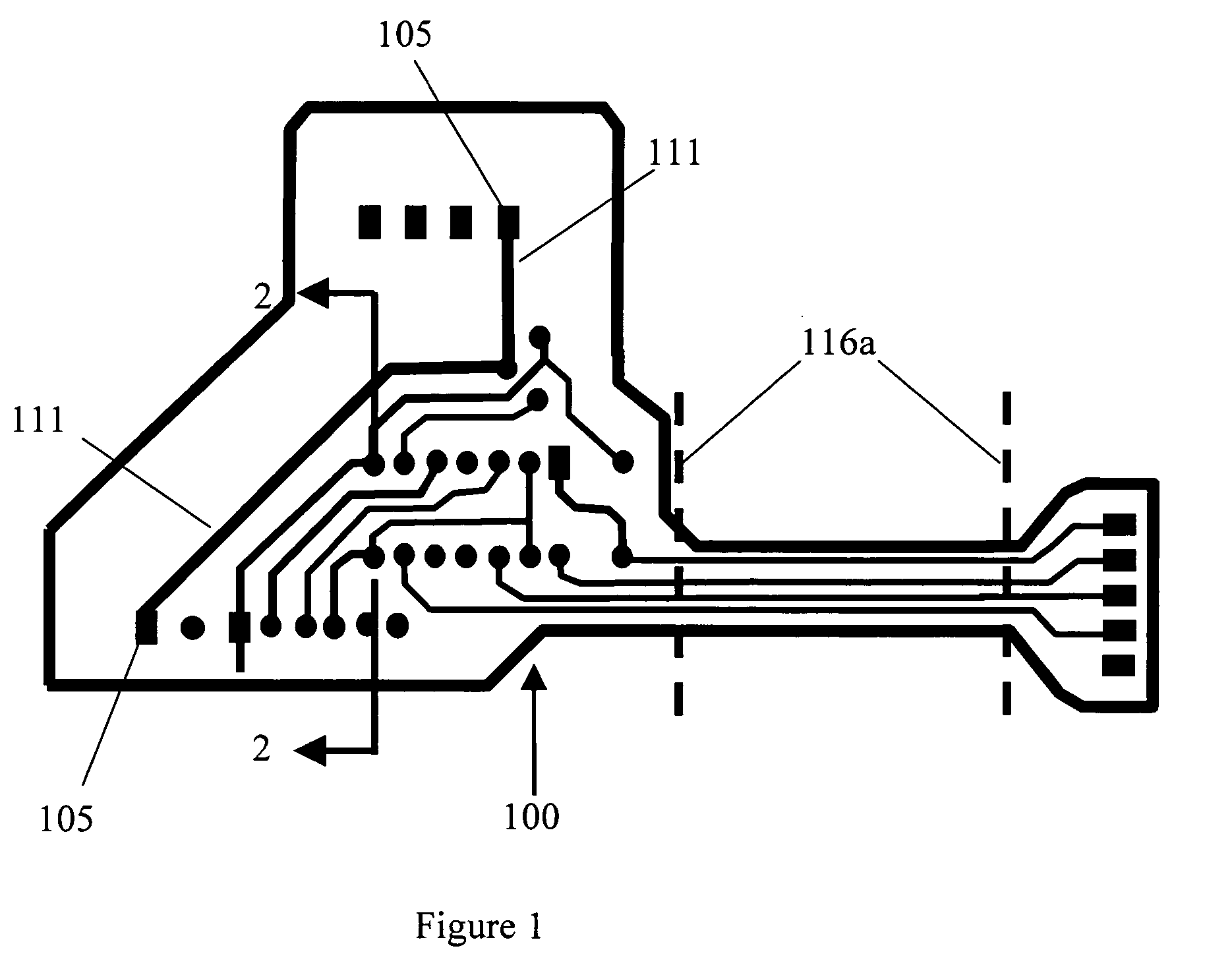
[0060]FIG. 1 shows a top view of rigid core portion 100 with electrical pads 105 and traces 111, according to a preferred embodiment of the present invention.

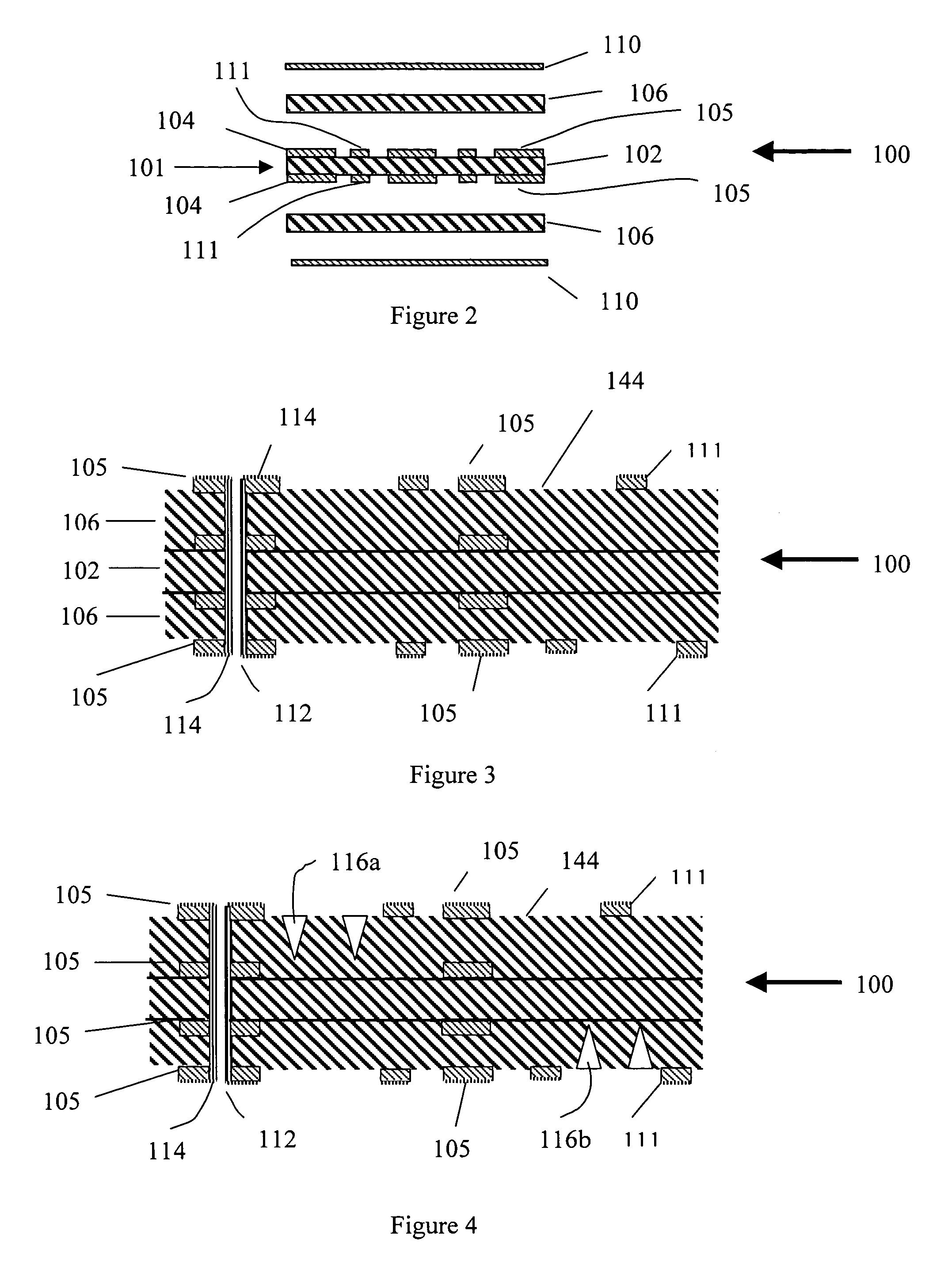
[0061]FIG. 2 shows an exploded side view of rigid core portion 100 of rigid-flex circuit board system 200 according to a preferred embodiment of the present invention. Preferably rigid-flex circuit board system 200 comprises rigid core portion 100, as shown. Preferably, rigid core portion 100 comprises at least one inner layer 101. Preferably inner layer 101 comprises at least one substantially rigid insulating layer 102. Preferably, rigid insulating layer 102 comprises epoxy reinforced with fiberglass. Upon reading the teachings of this specification, those with ordinary skill in the art will now understand that, under appropriate circumstances, considering issues such as production cost, intended use, advances in materials and technology, etc., other rigid insulating layer arrangements may suffice, such as, for example, other...


PUM

PropertyMeasurementUnit
thickaaaaaaaaaa
thickaaaaaaaaaa
flexibleaaaaaaaaaa

Abstract

A rigid-flex circuit board system that can be manufactured using less expensive and more reliable rigid circuit board methods and equipment, and can maintain rigidity and dimensional stability until the time when it is first desired to flex.

Description

CROSS-REFERENCE TO RELATED APPLICATION[0001]The present application claims the benefit of provisional application Ser. No. 60 / 431,239, filed Dec. 6, 2002, entitled “FLEXIBLE PRINTED CIRCUIT BOARD AND METHOD FOR THE FABRICATION THEREOF”, the contents of which are incorporated herein by this reference and is not admitted to be prior art with respect to the present invention by the mention in this cross-reference section.BACKGROUND[0002]This invention relates to providing a rigid-flex circuit board system which can be produced more efficiently and has greater functionality than prior art rigid-flex circuit boards. In the past, manufacturing rigid flex circuit boards has been problematic. Many factors, difficult to control given current manufacturing techniques, result in high scrap rates (circuit boards that do not work). For example, in the past, it has been troublesome to align flexible printed circuit layers with rigid printed circuit layers since the flexible printed circuit layers...

Claims


Application Information

Patent Timeline
Patent Type & Authority Patents(United States)
IPC IPC(8): H05K1/03H05K1/00H05K1/11H05K1/16H05K3/00H05K3/42
CPCH05K1/0278H05K3/4691H05K1/118Y10T29/49126H05K1/16H05K3/0032H05K3/0044H05K3/0061H05K3/429H05K2201/09036H05K2201/09081H05K2201/0909H05K2201/09109H05K2201/09536H05K2201/09745H05K2203/1572H05K2203/302
Inventor FLAMMER, JEFFREY D.FORCIER, ROBERT
Owner FLAMMER JEFFREY D
Features
  • R&D
  • Intellectual Property
  • Life Sciences
  • Materials
  • Tech Scout
  • Unparalleled Data Quality
  • Higher Quality Content
  • 60% Fewer Hallucinations
Learn More