Programmable-code electromagnetic transponder

a transponder and programmable code technology, applied in the field of electromagnetic transponders, can solve the problems of complexity adversely affecting the miniaturization and cost of present transponders, binary code, exorbitant operation price, etc., and achieve the effect of overcoming the disadvantages of conventional transponders

Inactive Publication Date: 2008-05-13
STMICROELECTRONICS SRL
View PDF17 Cites 11 Cited by
  • Summary
  • Abstract
  • Description
  • Claims
  • Application Information

AI Technical Summary

Benefits of technology

[0016]The present invention aims at overcoming the disadvantages of conventional transponders. In particular, the present invention aims at providing an electromagnetic transponder avoiding use of a digital modulator to transmit data stored in storage elements.
[0018]The present invention also aims at enabling simple programming of a binary code in an electromagnetic transponder. In particular, the present invention aims at avoiding use of a bidirectional communication to write a code in a transponder.

Problems solved by technology

A problem of conventional transponders is linked to the need to use a modulator-demodulator to convert a code (digital data, identification code of a label, etc.) to be transmitted to the read-write terminal.
This complexity adversely affects the miniaturization and the cost of present transponders.
Another disadvantage is that the programming of a binary code and, more generally, the writing of data in an electromagnetic transponder, requires at best a communication with a read-write terminal and a complex exchange protocol.
A disadvantage is the exorbitant price of the operation, which must be repeated for each chip.
Another disadvantage is that the processing is optically visible, and thus detectable.

Method used


Image

  • Programmable-code electromagnetic transponder
  • Programmable-code electromagnetic transponder
  • Programmable-code electromagnetic transponder

Examples


Embodiment Construction

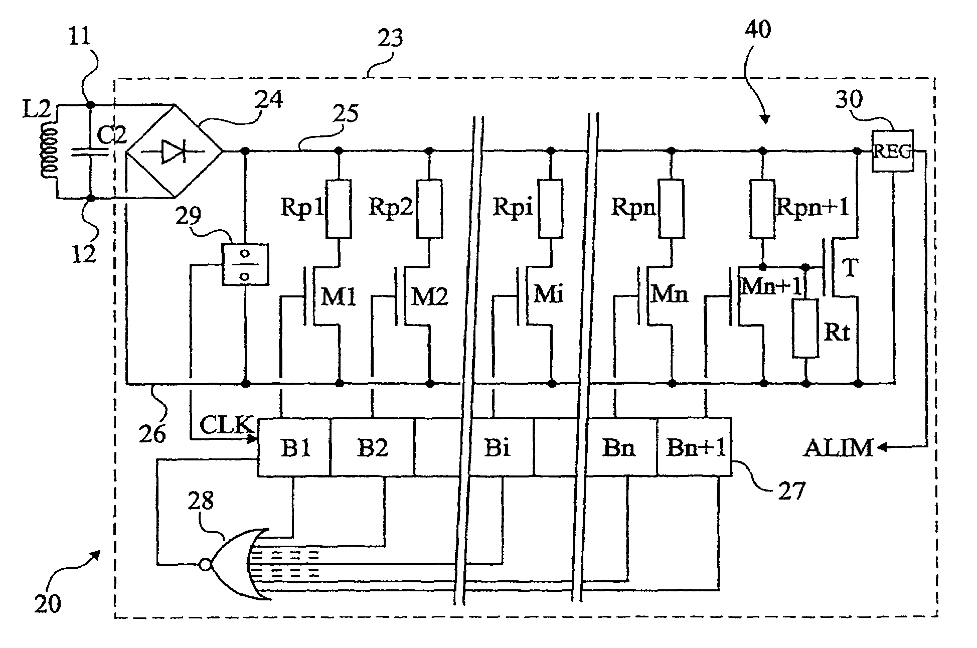
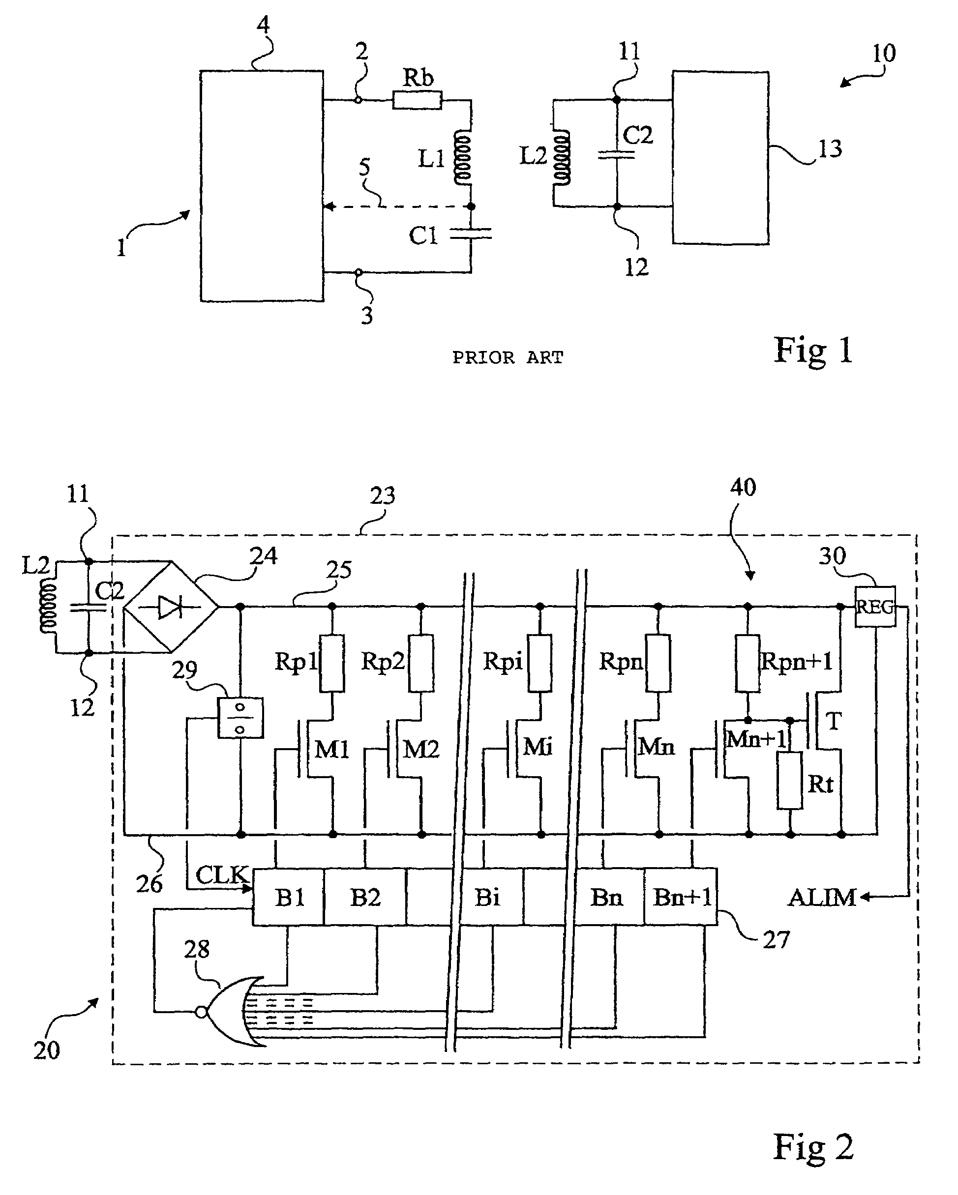
[0045]Same elements have been referred to with same references in the different drawings. For clarity, only those elements necessary to the understanding of the present invention have been shown in the drawings and will be described hereafter. In particular, the different circuits of reading and exploitation of the data recovered by a read-write terminal have not been detailed. The present invention may be implemented whatever exploitation is made of the data.

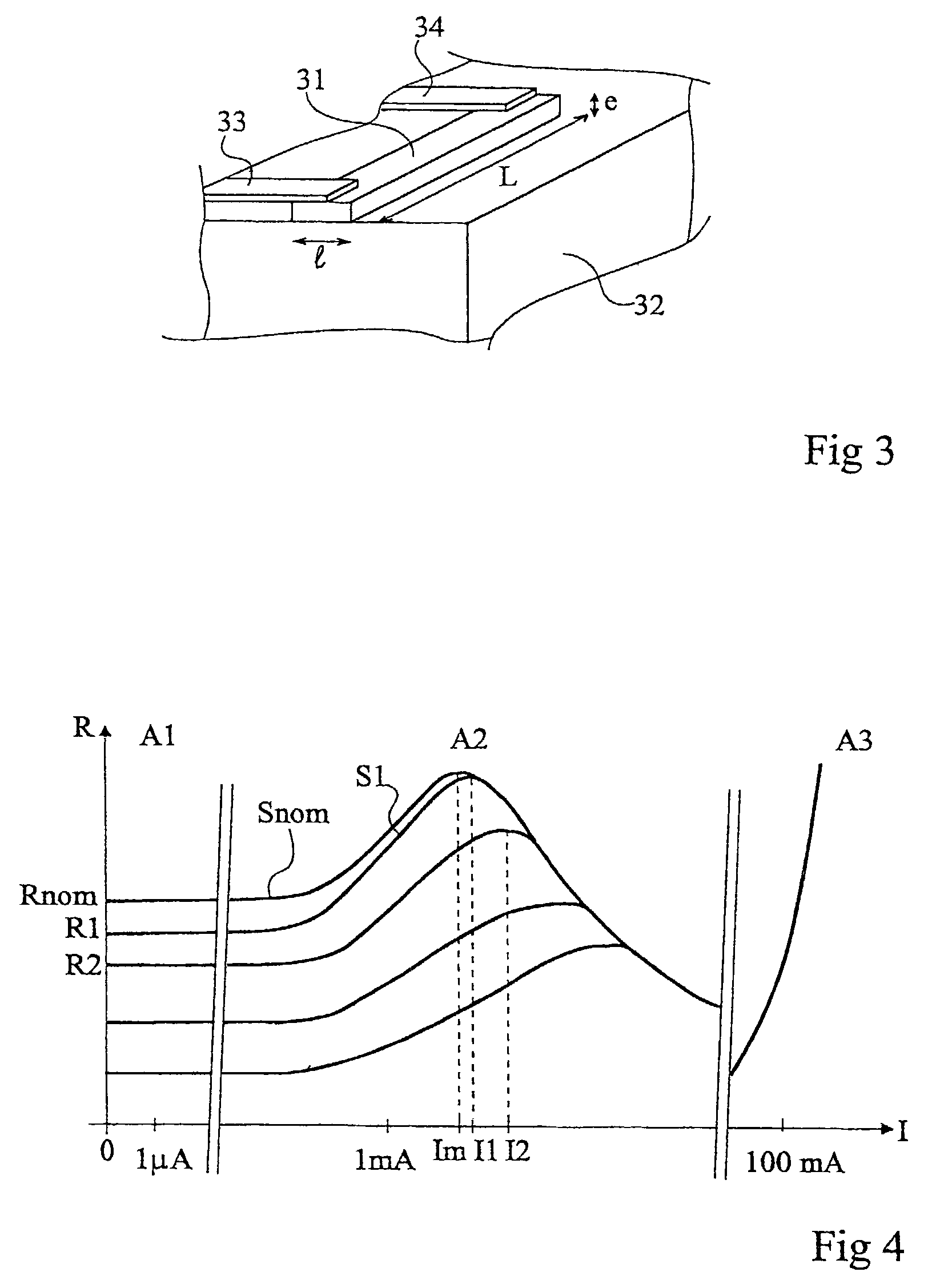
[0046]A feature of the present invention is to use, as the storage element of data to be transmitted, directly the resistance value of a back modulation element formed of a switch in series with a resistor. Thus, according to the present invention, several back-modulation elements are provided in parallel with the oscillating circuit to modify its load. Another feature of the present invention is that the resistances of the different elements have different values according to the state (for example, 0 or 1) of the code portion...


PUM


Abstract

An electromagnetic transponder including: a parallel oscillating circuit adapted to extracting a supply signal from a radiated field; in parallel with the oscillating circuit, several branches each including a programmable resistor and a switch; and a cyclic control element for successively turning on the switches, each resistor forming an element for storing a portion of the code stored in the transponder.

Description

BACKGROUND OF THE INVENTION[0001]1. Field of the Invention[0002]The present invention relates to an electromagnetic transponder, that is, a transceiver (most often, mobile) capable of being interrogated in a contactless and wireless manner by a unit (generally fixed), called a read and / or write terminal. Generally, transponders extract the power supply required by the electronic circuits included therein from a high frequency field radiated by an antenna of the read / write terminal. There exist read-only transponders, that is, transponders adapted to operating with a terminal which only reads transponder data, and read / write transponders, which contain data that can be modified by the terminal.[0003]2. Discussion of the Related Art[0004]Systems using electromagnetic transponders are based on the use of oscillating circuits including a winding forming an antenna, on the transponder side and on the read / write terminal side. These circuits are capable of being coupled by close magnetic ...

Claims


Application Information

Patent Timeline
Patent Type & Authority Patents(United States)
IPC IPC(8): H04Q5/22G06K19/067G06K19/07G06K19/077G11C17/14H04B1/59H04B5/02
CPCG06K19/067G06K19/0723G11C17/14G06K19/07
Inventor WUIDART, LUCBARDOUILLET, MICHEL
Owner STMICROELECTRONICS SRL
Why Eureka
Try Eureka