Transceiver-integrated antenna

a technology of integrated antennas and transceivers, applied in the direction of resonant antennas, substantially flat resonant elements, independent non-interacting antenna combinations, etc., can solve the problems of increasing the number of parts and high production costs of their production, and achieve the effects of reducing the production cost of the antenna, preventing noise emitted, and discharging hea

Active Publication Date: 2008-05-13
DENSO CORP
View PDF12 Cites 8 Cited by
  • Summary
  • Abstract
  • Description
  • Claims
  • Application Information

AI Technical Summary

Benefits of technology

[0018]In each of the above described structures, the ground plate serves as not only a plane for grounding the antenna element(s), but also a radiator for dissipating the heat emitted from the transceiver. Accordingly, with the present invention, the vehicle-installed integrated antenna can be constituted by a smaller number of parts, thereby reducing the production costs thereof. Furthermore, with the present invention, it is possible to prevent the noise emitted from the transceiver from leaking to the outside, because the transceiver can be housed in a shielded state.

Problems solved by technology

However, conventional transceiver-integrated antennas have a problem in that their production costs are high, because they must have a heat radiating member (or heat radiation fin) for dissipating the heat emitted from the transceiver in addition to a ground plate, which inevitably increases the number of parts.

Method used


Image

  • Transceiver-integrated antenna
  • Transceiver-integrated antenna
  • Transceiver-integrated antenna

Examples


Embodiment Construction

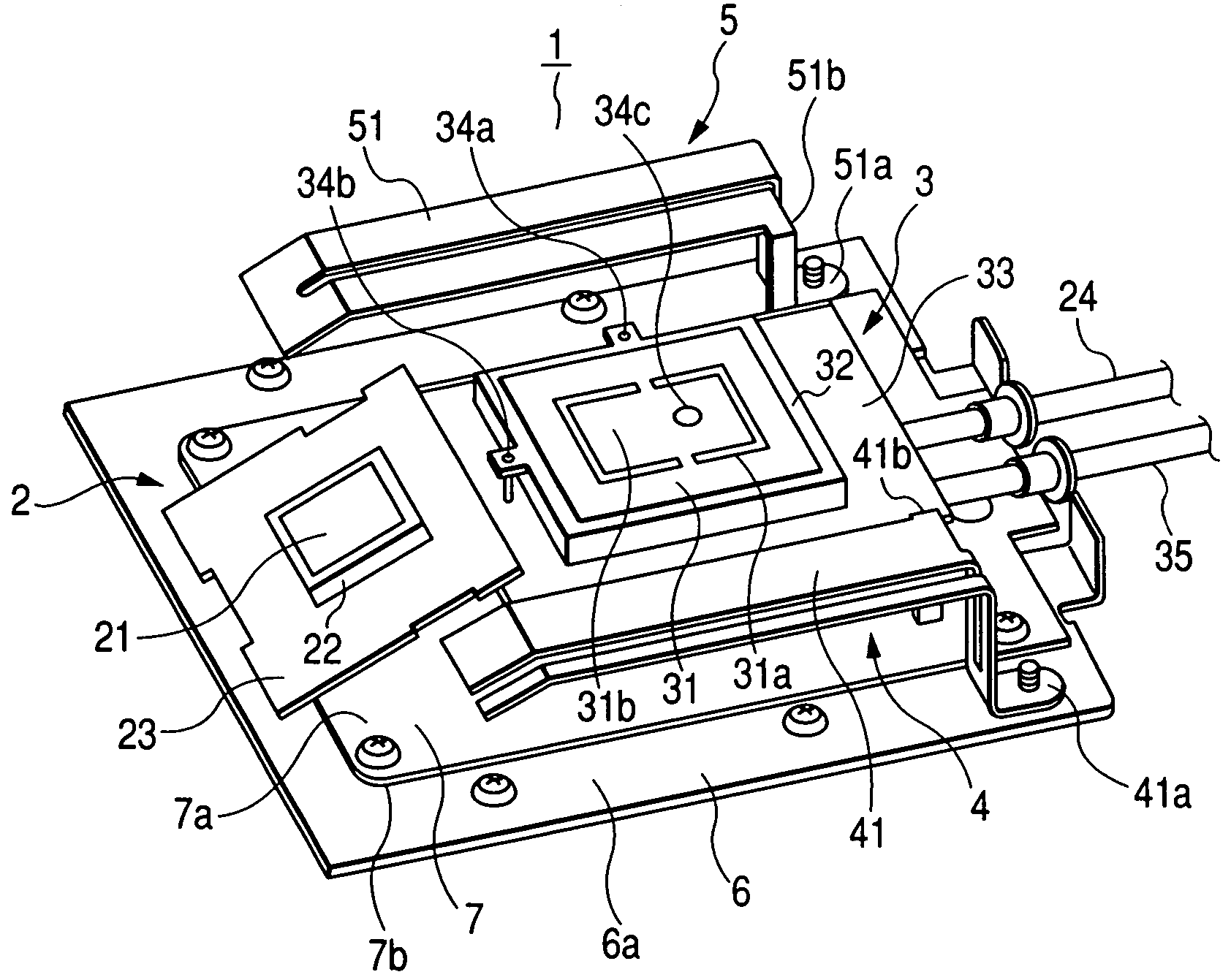
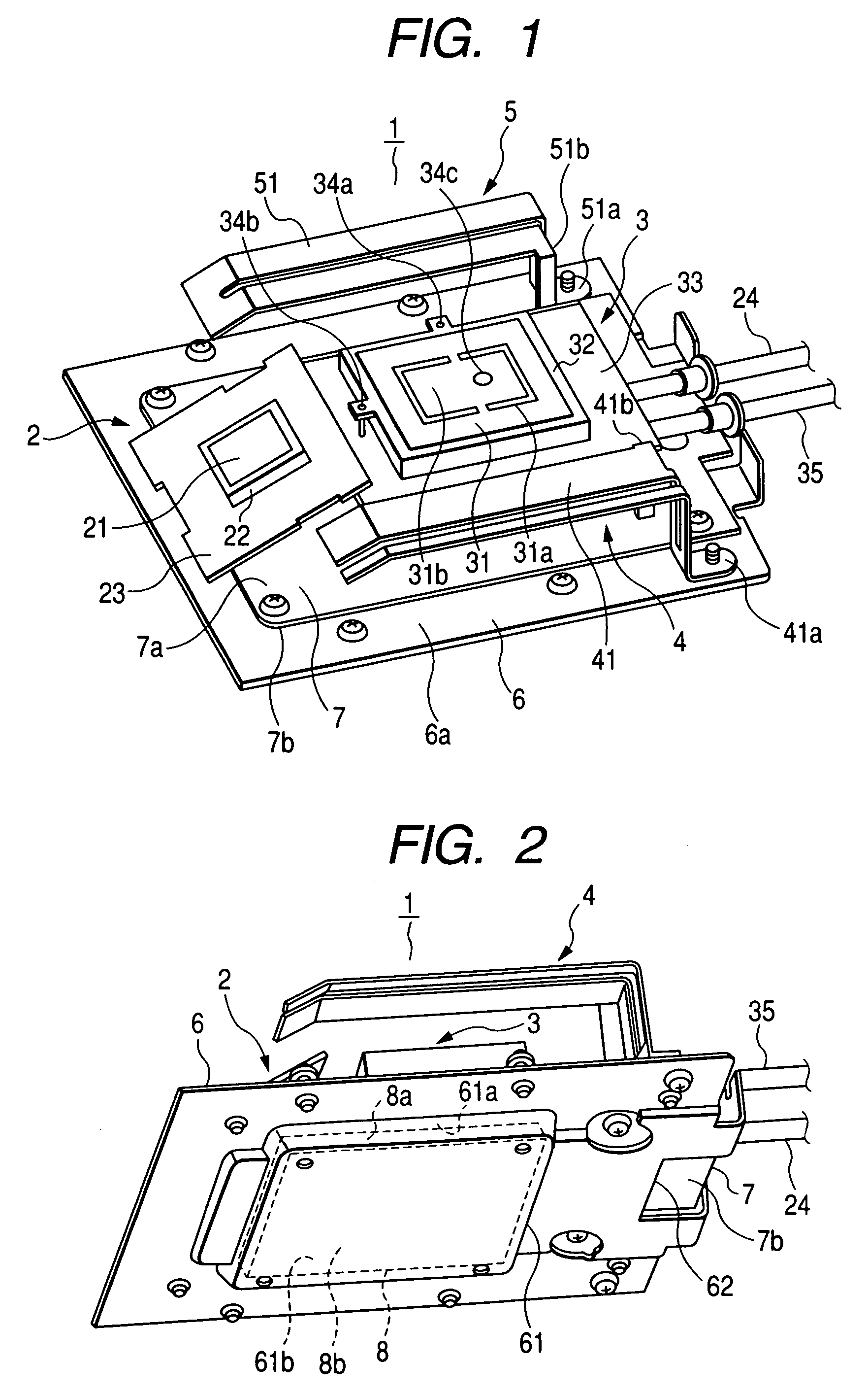
[0022]FIG. 1 is a perspective view of a vehicle-installed type transceiver-integrated antenna 1 (referred to as vehicle-installed integrated antenna 1, or integrated antenna 1 hereinafter) according to an embodiment of the invention viewed from above. This integrated antenna 1 includes an antenna element 2 for the ETC (Electronic Toll Collection system), an antenna element 3 for GPS (Global Positioning System) / VICS (Vehicle Information Communications System), and telephone antenna elements 4 and 5 for the automobile telephone system.

[0023]The ETC antenna element 2 is constituted by an ETC circuit board 23, a rectangular parallelepiped dielectric 22 mounted on the ETC circuit board 23, and a rectangular electrode 21 formed on the dielectric 22.

[0024]The ETC antenna element 2 is connected to one end of a coaxial cable 24 the other end of which is connected to an ETC connector (not shown) connectable to an ETC transceiver (not shown). The ETC antenna element 2 is installed such that it...


PUM


Abstract

The transceiver-integrated antenna includes an antenna element, a ground plate for grounding the antenna element, and a transceiver configured to transmit and receive radio signals through the antenna element. The transceiver is housed in a recess formed in the ground plate. The ground plate serves as not only a plane for grounding the antenna element, but also a radiator for dissipating the heat emitted from the transceiver.

Description

CROSS-REFERENCE TO RELATED APPLICATION[0001]This application is related to Japanese Patent Application No. 2004-212927 filed on Jul. 21, 2004, the contents of which are hereby incorporated by reference.BACKGROUND OF THE INVENTION[0002]1. Field of the Invention[0003]The present invention relates to a transceiver-integrated antenna including an antenna element, and a transceiver which is integrated to the antenna element and configured to transmit and receive radio signals through the antenna element.[0004]2. Description of Related Art[0005]As described, for example, in Japanese Patent Application Laid-open No. 2002-111377, it is known to use an integrated antenna including a plurality of different antenna elements used for different radio communication systems for the purpose of saving antenna installation space. It is also known to use a transceiver-integrated antenna including an antenna element and a transceiver for the purpose of saving antenna installation space, and also reduci...

Claims


Application Information

Patent Timeline
Patent Type & Authority Patents(United States)
IPC IPC(8): H01Q1/24
CPCH01Q1/3208H01Q1/38H01Q1/48H01Q9/0407H01Q9/42H01Q21/28
Inventor KOIDE, SHIROU
Owner DENSO CORP
Why Eureka
Try Eureka