Telecommunication loose tube optical cable with reduced diameter

a loose tube, optical cable technology, applied in the direction of optics, instruments, optical light guides, etc., can solve the problems of insufficient utilization of technical and economic advantages, inability to optimize the number of fibres of terrestrial cables with medium or high potentiality, and insufficient installation of similar cables

Active Publication Date: 2008-05-13
PRYSMIAN CAVI E SISTEMI ENERGIA
View PDF6 Cites 41 Cited by
  • Summary
  • Abstract
  • Description
  • Claims
  • Application Information

AI Technical Summary

Benefits of technology

[0033]Preferably, the external cable-diameter is ≦about 7.0 mm, more preferably ≦about 6.0 mm with a number of optical fibers ≧72.
[0034]Preferably, the outer jacket is made of a material selected

Problems solved by technology

As the replacement is submitted to the effective final client requests and is rather expensive for a telecommunication provider, some providers use to arrange a network made only of empty plastic conduits and to install the optical fiber cables in the conduits only when proper requests from the clients have been received.
Most of the existing terrestrial cables having a medium or high potentiality in terms of number of fibres are not optimized for being blown installed into miniaturized tubes and do not allow to exploit the whole technical and economical advantages of the blown cable installation method.
According to the Applicant,

Method used


Image

  • Telecommunication loose tube optical cable with reduced diameter
  • Telecommunication loose tube optical cable with reduced diameter
  • Telecommunication loose tube optical cable with reduced diameter

Examples


Embodiment Construction

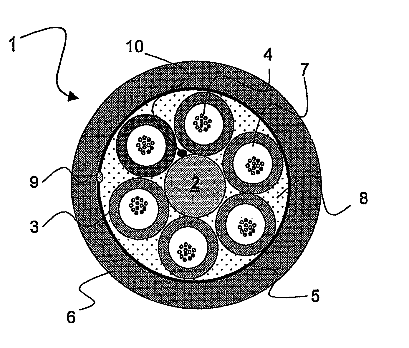
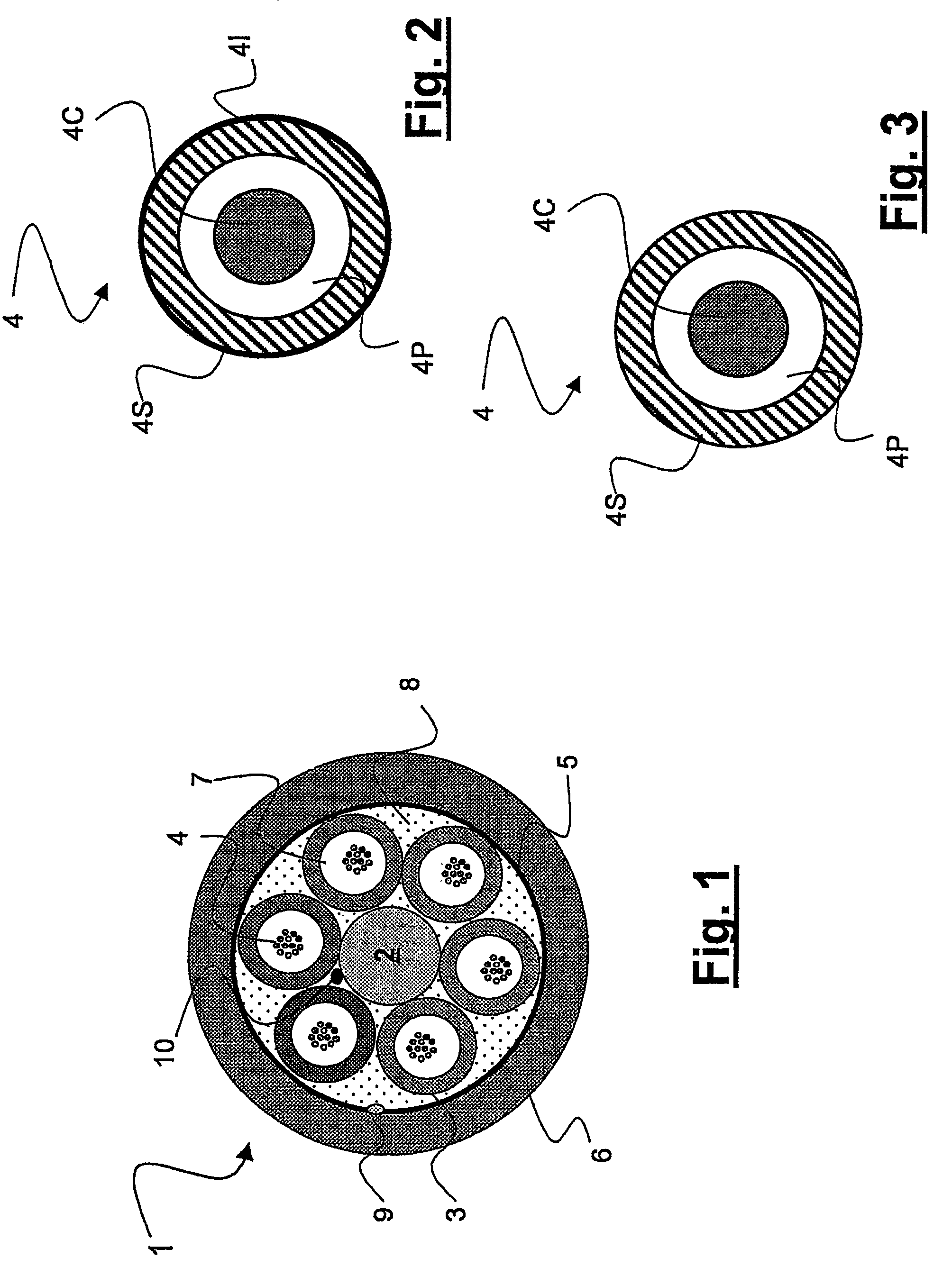
[0039]With reference to FIG. 1, a multi loose tube (MLT) cable 1 comprises: a central strength member 2; a number of tubes 3 arranged around the central strength member 2 and housing loosely placed optical fibers 4; a mechanical reinforcing layer 5 (if necessary for cable tensile load withstanding), for example a thread made of glass or of an aramid material, arranged around the tubes; and a protective outer jacket 6 surrounding the reinforcing layer.

[0040]The tubes 3 containing the optical fibers 4 are typically stranded around the central rod 2 according to an unidirectional helix or a bidirectional (SZ) helix. The stranded tubes 3 and the central rod enclosed therebetween define a so called “stranded tube core”. Preferably, the tubes 3 are filled of jelly 7 or the like. Alternatively, the tube 3 may be filled with igro-expanding agents, such as powders or filaments. Similarly, the interstices between central rod 2, tubes 3 and outer jacket 6 are filled of igro-expanding agents 8,...


PUM


Abstract

An optical fiber cable has a highly reduced diameter. The cable has a central strength member; a number of tubes containing loosely arranged optical fibers, each tube having a thickness, and each optical fiber having a coating; and a protective outer jacket, wherein the filling coefficient of optical fibers in at least one loose tube is ≧45°/0. The tubes are made of a material having an elasticity modulus ≧700 MPa; and the optical fibers are SM-R fibers having a microbending sensitivity ≦4.0 dB·km−1/g·mm−1 at a temperature of about −30° C. to +60° C. at about 1550 nm.

Description

CROSS REFERENCE TO RELATED APPLICATION[0001]This application is a national phase application based on PCT / EP2003 / 010913, filed Sep. 30, 2003, the content of which is incorporated herein by reference.BACKGROUND OF THE INVENTION[0002]1. Field of the Invention[0003]The present invention relates to telecommunication optical cables and in particular it relates to a telecommunication optical cable having a highly reduced diameter, which is particularly suitable for being installed in conduits by a “blown method”.[0004]2. Description of the Related Art[0005]Access and trunk telecommunication networks made by copper wires are being replaced by optical fiber networks in view of their large bandwidth capabilities. As the replacement is submitted to the effective final client requests and is rather expensive for a telecommunication provider, some providers use to arrange a network made only of empty plastic conduits and to install the optical fiber cables in the conduits only when proper reque...

Claims


Application Information

Patent Timeline
IPC IPC(8): G02B6/44
CPCG02B6/441G02B6/443G02B6/4434
Inventor PIZZORNO, MASSIMOGINOCCHIO, ALESSANDROCONSONNI, ENRICO
Owner PRYSMIAN CAVI E SISTEMI ENERGIA
Why Eureka
Try Eureka