Brake monitoring system for heavy vehicles

a technology for monitoring systems and brakes, applied in braking systems, brake components, instruments, etc., can solve problems such as inability to perform tasks, slack adjustors, and sometimes failing to operate or become inoperabl

Active Publication Date: 2008-05-13
SAFETY WATCH TECH
View PDF5 Cites 28 Cited by
  • Summary
  • Abstract
  • Description
  • Claims
  • Application Information

AI Technical Summary

Benefits of technology

[0016]An object of the invention is to provide an automatic brake-travel monitoring system that is simple and reliable, easy for the operator to use, is inexpensive to install and maintain, and is readily adaptable to various axle configurations.
[0017]An object of the instant invention is to provide a brake monitoring and warning system which will provide a continuous check on the safety condition of the brakes on the vehicle.
[0019]A further object of the invention is to provide a system which provides a quantitative display of the travel of any given brake on the vehicle and provides information to the operator as to the overall operating condition of the brake system for the vehicle.

Problems solved by technology

Even with the self-adjusting brakes, the slack adjustors, as they are known in the trade, will sometimes fail to operate or will become inoperative as a result of the build up of petrochemical products, dirt or ice in the slack adjustment mechanism, which allows brakes to be out of adjustment.
As might be expected, this task is not always performed, particularly in inclement weather conditions.
There have been a few attempts to build and market such systems in the industry, however, all known systems suffer from one or more serious defects.
Some require extensive and expensive modifications to the vehicle and brake system, others are difficult or inconvenient to use, and still others are not readily adaptable to the wide variety of axle configurations found on modern trucks.
U.S. Pat. No. 5,285,190 for Automatic slack adjuster with operation and adjustment monitor, to Humphries, et al., granted Feb. 8, 1994, disclosed an automatic slack adjustor which incorporates a monitoring system alerting the vehicle operator that a brake somewhere on the vehicle is not operating properly, or is out of adjustment, but does not provide any mechanism for identifying the specific brake that is out of adjustment, nor does the system identify any quantitative information about a particular brake.

Method used


Image

  • Brake monitoring system for heavy vehicles
  • Brake monitoring system for heavy vehicles
  • Brake monitoring system for heavy vehicles

Examples


Embodiment Construction

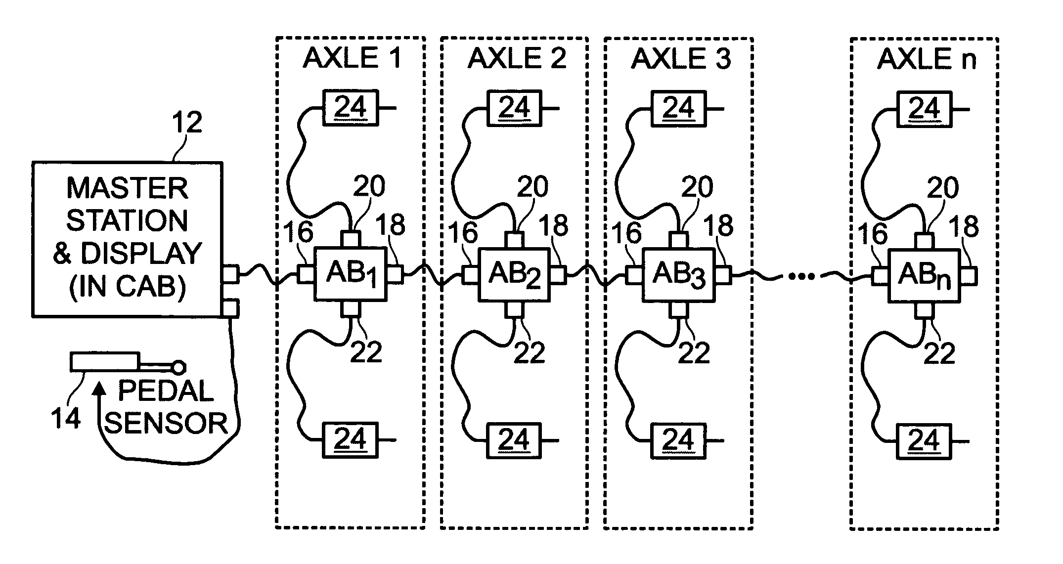
[0029]There are three features of the system of the invention described herein. The first is a brake-travel monitoring system, which is applicable to a vehicle having any number of axles. The second is a sensor installed adjacent a wheel to monitor brake travel. The third is an automatic and adaptive addressing system for monitoring individual brakes in a multiple axle vehicle.

Brake Travel Monitoring System

[0030]It is desirable to monitor heavy vehicle brakes for safe operation. In large trucks, fairly common and very dangerous situations occur when one or more of the wheel brakes become inoperative. This is usually a result of failure of the automatic brake slack-adjusting mechanism, or failure of a driver to insure proper brake adjustment. When excessive brake travel occurs, eventually the brake shoes no longer properly contact the brake drums, and the brakes become inoperative.

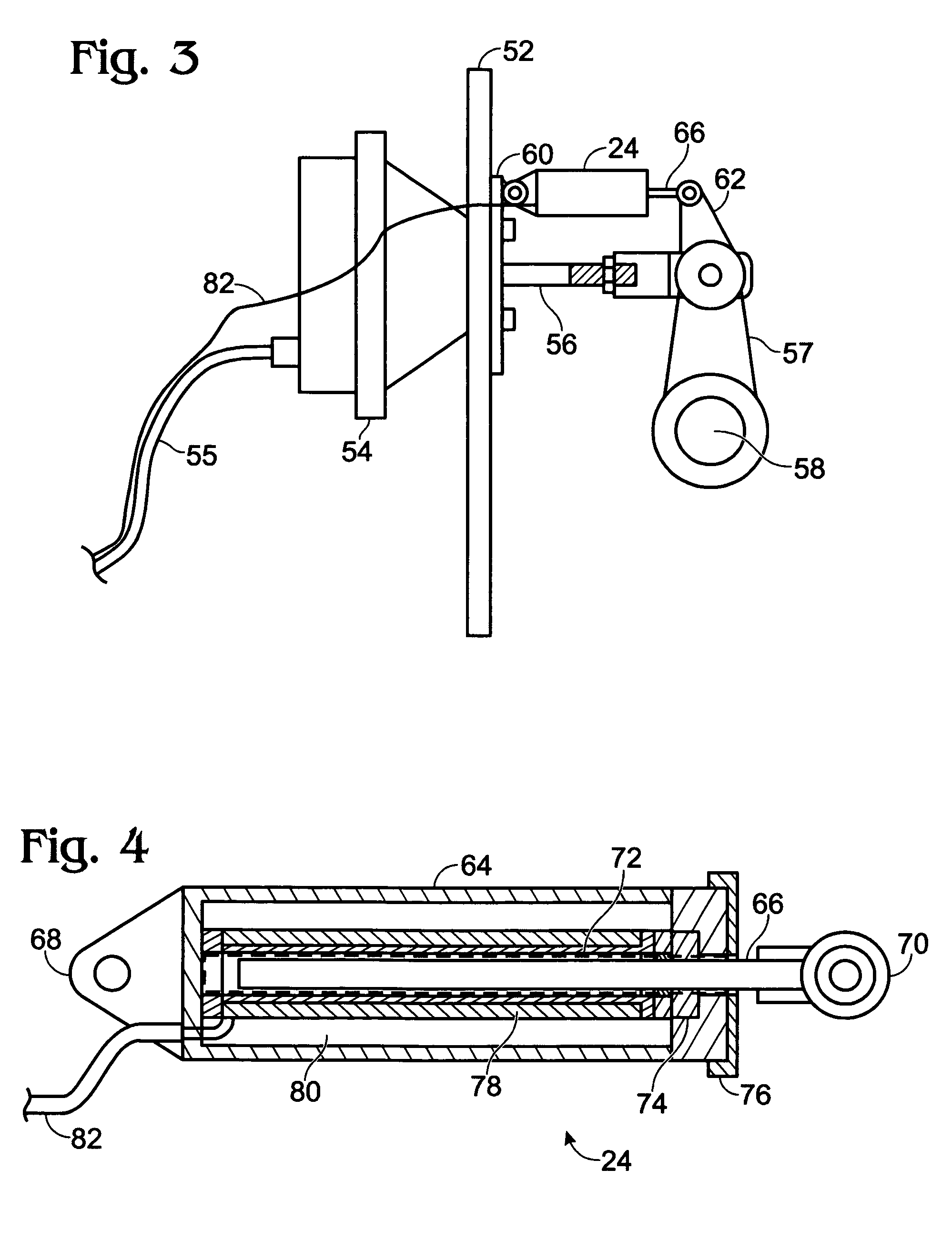
[0031]The key symptom of this problem is excessive travel of the brake actuation linkage. For normal bak...


PUM


Abstract

A brake monitoring system for use on a motor vehicle includes a sensor connected to each brake actuator shaft on the motor vehicle for monitoring the position and travel of the brake actuator shaft and for generating and transmitting a brake condition signal; a data processor carried in an axle box associated with each axle and connected to sensors associated with brakes for the axle for receiving, interpreting, storing, and upon request, transmitting the brake condition signal, wherein each data processor includes an auto-address mechanism to identify its position on the vehicle; and a master station, wherein said master station includes a display for identifying a particular vehicle brake, a quantitative indication of the travel on the brake actuator shaft associated with the particular brake, and wherein said visual indicating devices include plural indicia which are indicative of said safety condition of a particular brake.

Description

FIELD OF THE INVENTION[0001]This invention relates to monitoring systems for multi-axle, heavy vehicles, such as trucks and busses, and specifically to a system which automatically identifies the number of axles and brakes on a vehicle to be monitored.BACKGROUND OF THE INVENTION[0002]Although the primary intended use of this invention is on large trucks and tractor-trailer combinations, it should be appreciated that the invention is also suitable for use on all vehicles which have independent brakes for each wheel, such as vehicles which generally incorporate an air-brake system. These brakes must be properly adjusted in order properly to function. Various standards have been set by state governments and the Federal Department of Transportation (DOT) to insure that brakes are properly adjusted and are therefore operable to stop these heavy vehicles when the need arises.[0003]One standard that has been set by the DOT is a requirement that the travel of an actuator rod, which extends ...

Claims


Application Information

Patent Timeline
Patent Type & Authority Patents(United States)
IPC IPC(8): G06F19/00
CPCB60T17/22H04L61/5038
Inventor GOETZ, HOWARD V.DUFFY, DENNIS A.GOETZ, RANDALL J.RADY, ANDREW
Owner SAFETY WATCH TECH
Why Eureka
Try Eureka