Attachable guide for a circular saw

a circular saw and guide technology, applied in the field of carpentry tools, can solve the problems of requiring several steps and time-consuming process of laying out angles, and achieve the effect of simplifying the task of carpenters, attaching easily and securely

Inactive Publication Date: 2008-05-20
BAIDA NICHOLAS
View PDF16 Cites 15 Cited by
  • Summary
  • Abstract
  • Description
  • Claims
  • Application Information

AI Technical Summary

Benefits of technology

[0007]According to another aspect of the invention, the attachable guide may include a ball catch mechanism for regulating the amount of movement between the attaching and extension members. More particularly, a spring-loaded ball may be inserted through a hole in the attaching member and reside in a complementary channel defined by the extension member. However, when the ball encounters an end of the channel, it prevents further travel of the extension member, e.g. so as to prevent a complete separation of the extension and attaching members.
[0009]Therefore, a general object of this invention is to provide a guide for attachment to a circular saw for simplifying a carpenter's task of measuring, marking, and guiding the cutting of an angle in a workpiece.
[0010]Another object of this invention is to provide a tool, as aforesaid, which attaches easily and securely to a circular saw.
[0013]A further object of this invention is to provide a guide, as aforesaid, having a ball catch for selectively preventing the miter gauge from completely sliding out of the slotted member.

Problems solved by technology

Laying out and marking the angles can be a very time consuming process that may require several steps.

Method used


Image

  • Attachable guide for a circular saw
  • Attachable guide for a circular saw
  • Attachable guide for a circular saw

Examples


Embodiment Construction

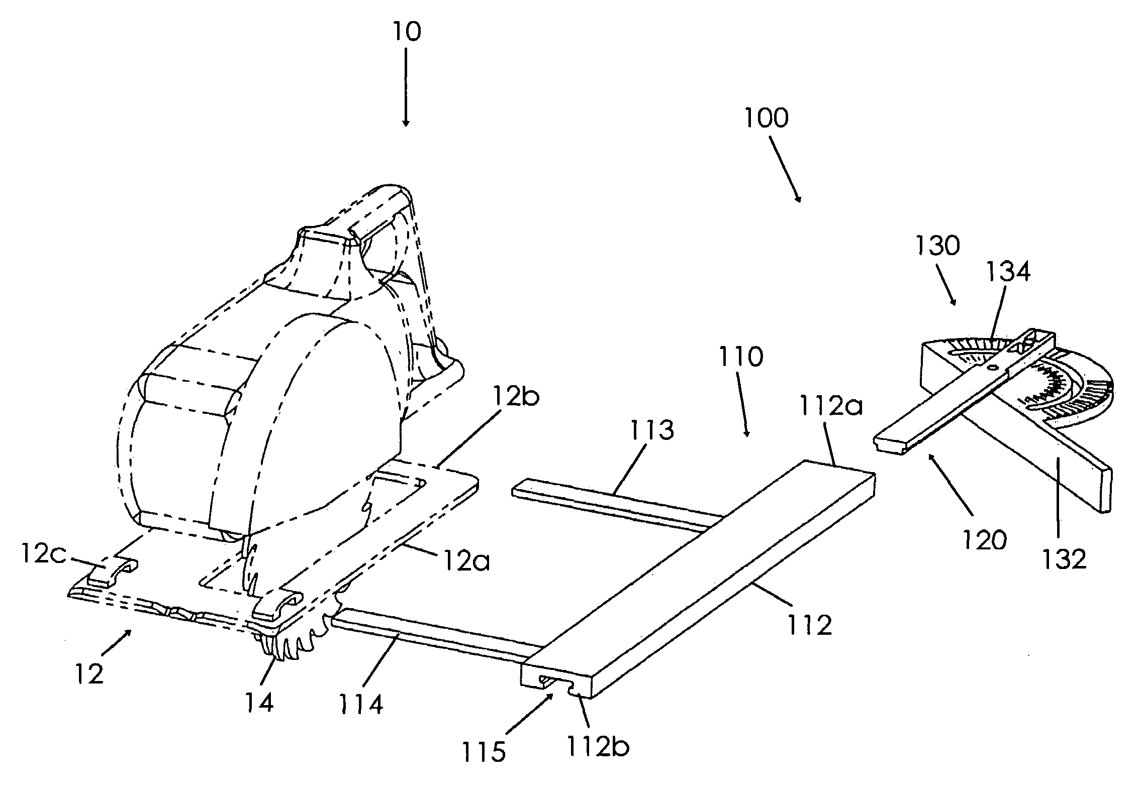
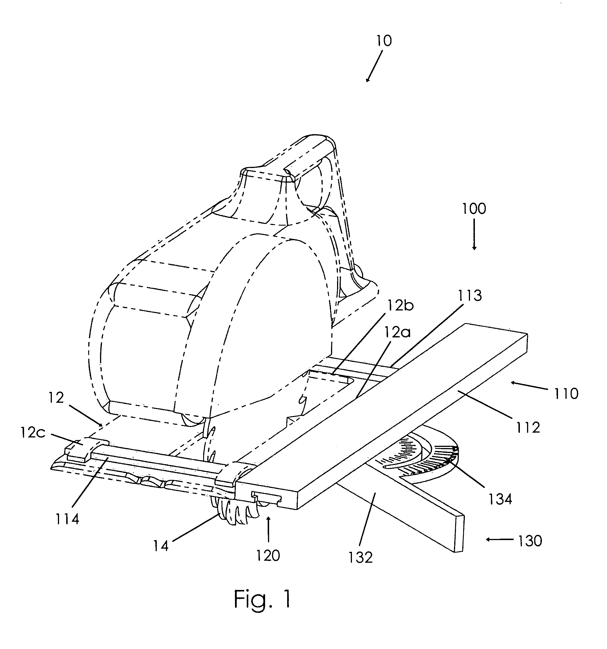
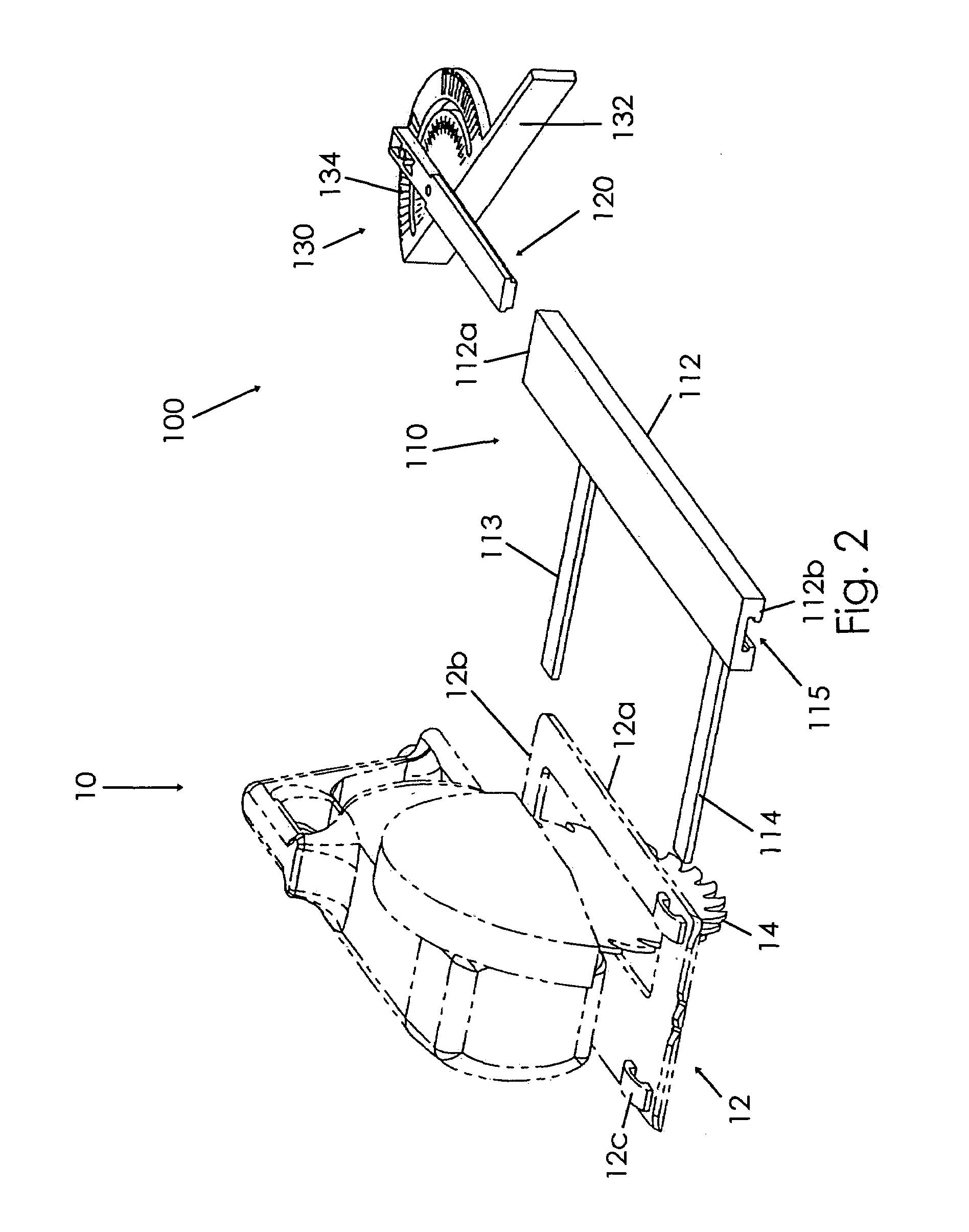
[0030]An attachable guide 100 for a circular saw 10 according to the present invention will now be described in detail with reference to FIGS. 1 through 9b of the accompanying drawings. More particularly, an attachable guide 100 according to the current invention includes an attaching member 110 and an extension member 120.

[0031]As shown in FIG. 1, the attaching member 110 may be selectively coupled to a shoe 12 of the circular saw 10. The attaching member 110 may have a primary portion 112 for abutting a side 12a of the shoe 12 and means for coupling the primary portion 112 to the shoe 12. More particularly, the attaching member 110 may have a rear portion 113 for abutting a rear surface 12b of the shoe 12 and a front portion 114 receivable in the shoe's rip guide slot 12c. The attaching member primary portion 112 has first and second ends 112a, 112b and defines a slot 115 extending from the first end 112a toward the second end 112b. The slot 115 is shown extending to the second en...


PUM

PropertyMeasurementUnit
angleaaaaaaaaaa
cutting anglesaaaaaaaaaa
timeaaaaaaaaaa

Abstract

A guide for attachment to a circular saw includes an attaching member, an extension member for slidable movement in a slot defined longitudinally along the attaching member, and an angle guide attached to the extension member. The attaching member is attachable to a circular saw rip guide and includes primary and rear portions for abutting a workpiece. The angle guide may be set to a desired angle and locked into place. With the angle guide pressed against the workpiece, the circular saw may be activated. As the saw and attached guide move forward along a cut path, the extension member and angle gauge remain abutted against the workpiece through relative slidable movement between the attaching and extension members. A ball catch mechanism may be included to selectively prevent the attaching and extension members from completely separating. A laser light may also be included to illuminate the line to be cut.

Description

BACKGROUND OF THE INVENTION[0001]This invention relates generally to carpentry tools and, more particularly, to a guide for attachment to a circular saw that simplifies laying out and cutting angles with a circular saw.[0002]A frequent task for a carpenter is to lay out angles on a workpiece such as a board and then to cut the piece along that angle. Laying out and marking the angles can be a very time consuming process that may require several steps. For instance, a carpenter may use a speed square or other angle-measuring device and then mark the angle with a pencil. Then the workpiece is taken to a saw or the saw, such as a circular saw, is brought to the workpiece where a cut is made. Of course, the accuracy of the cut is dependent upon the accuracy of the angle measurement and marking.[0003]Various devices have been proposed in the art for combining an angle measurement tool with a circular saw. Although assumably effective for their intended purposes, there is still a need for...

Claims


Application Information

Patent Timeline
Patent Type & Authority Patents(United States)
IPC IPC(8): B43L7/12B23Q17/22
CPCB23D59/003B23Q9/0085B27B9/04
Inventor BAIDA, NICHOLAS
Owner BAIDA NICHOLAS
Why Eureka
Try Eureka