Ergonomic fish tape

a tape and ergonomic technology, applied in the field of fish tapes, can solve the problems of requiring significant force, difficult to wind and unwind the tape, and virtually impossible to push through long conduit lengths

Inactive Publication Date: 2008-05-20
POWER PROD
View PDF10 Cites 5 Cited by
  • Summary
  • Abstract
  • Description
  • Claims
  • Application Information

AI Technical Summary

Benefits of technology

[0013]The present invention is a fish tape device with improved ergonomics and features designed to facilitate winding the fish tape onto the reel assembly.
[0019]In preferred forms, the winder includes a clutch such that rotating the winder handle in one direction rotates the housing with respect to its handle member to wind the fish tape, and rotating the winder handle in an opposite direction does not cause the housing to rotate relative to the handle member. The clutch is preferably a conventional drawn cup roller clutch available commercially. Also, the winder is removably mounted to the inner periphery of the reel assembly housing. Even more preferably the winder hub can be spaced from at least one interior grip surface of the inner periphery of the reel assembly housing so that the housing can also be rotated by grasping the grip.

Problems solved by technology

Because typical electrical wire is very flexible, pushing it through long lengths of conduit is virtually impossible.
This reel arrangement makes it somewhat difficult to wind and unwind the tape.
Given the relative rigid and springy characteristics of the fish tape, coiling the fish tape can require significant force and can be time consuming and frustrating, particularly if the tape binds inside of the reel.
While this design provides significant benefits over other conventional fish tape reels, it lack ergonomic features that make it comfortable to operate.
One common problem with conventional fish tape reels is that the handle, as in U.S. Des. Pat. No. D408,749, is ordinarily a carrying handle for transporting the reel to and from a job site, for example, rather than being something to grip and brace the reel when unwinding, and especially, when winding the fish tape.
However, the disclosed reel coils the fish tape in a cavity located horizontally behind the handle such that the reel would tend to cock back under the force of gravity and forces generated during the winding and unwinding processes such that user's wrist will have to overcome these forces, thereby straining the user's wrist.
This location, in which the handle of the threader is positioned at a front side of the reel, is disadvantageous because the weight of the reel will tend to cause the wrist to cock backward, especially when winding the fish tape.

Method used


Image

  • Ergonomic fish tape
  • Ergonomic fish tape
  • Ergonomic fish tape

Examples


Embodiment Construction

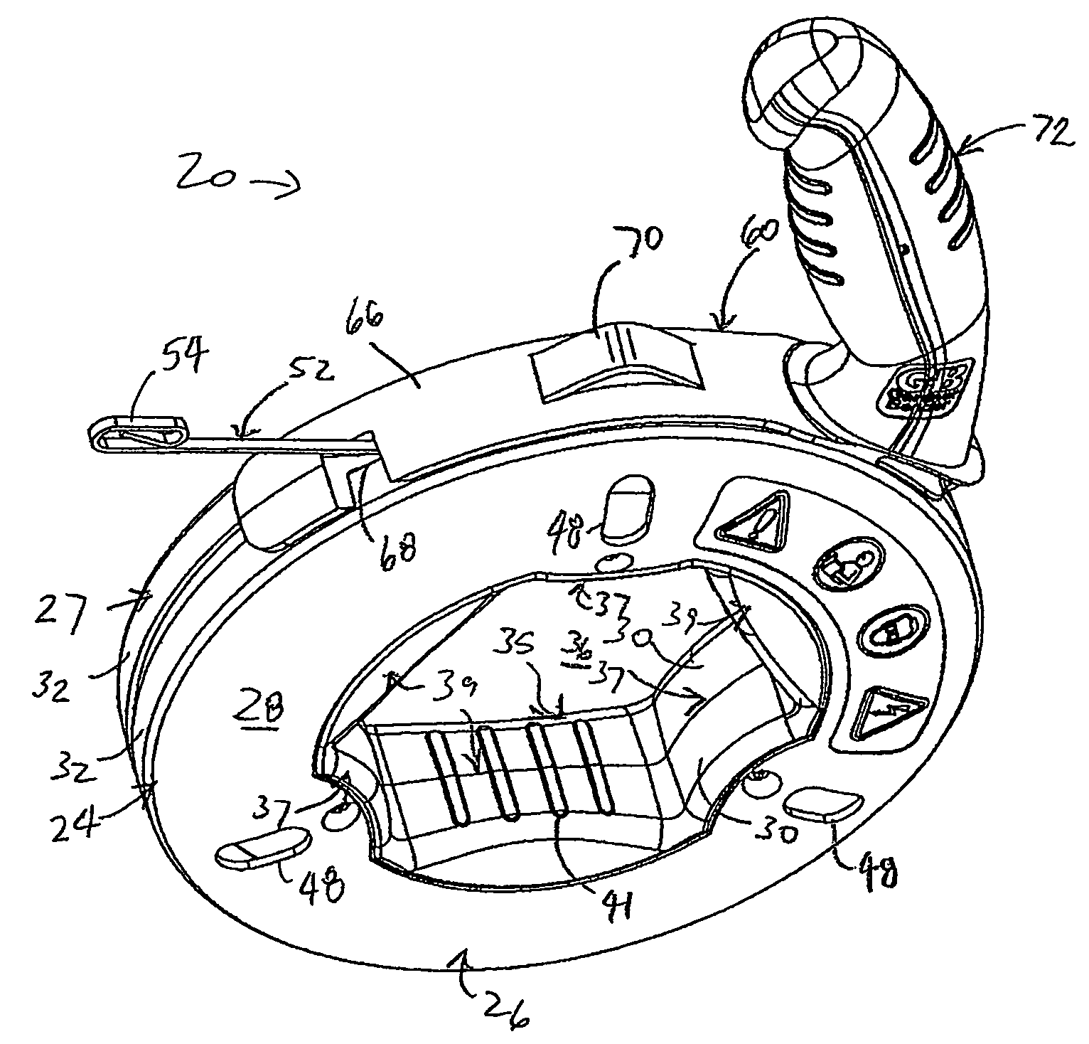
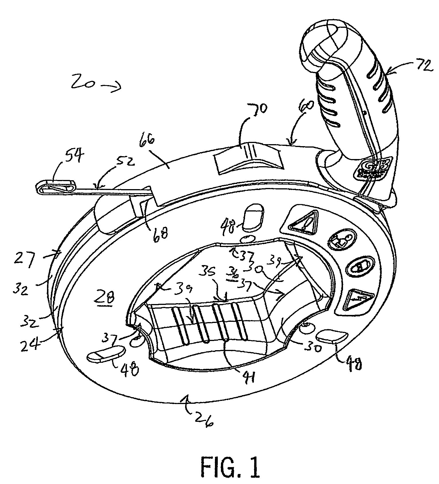
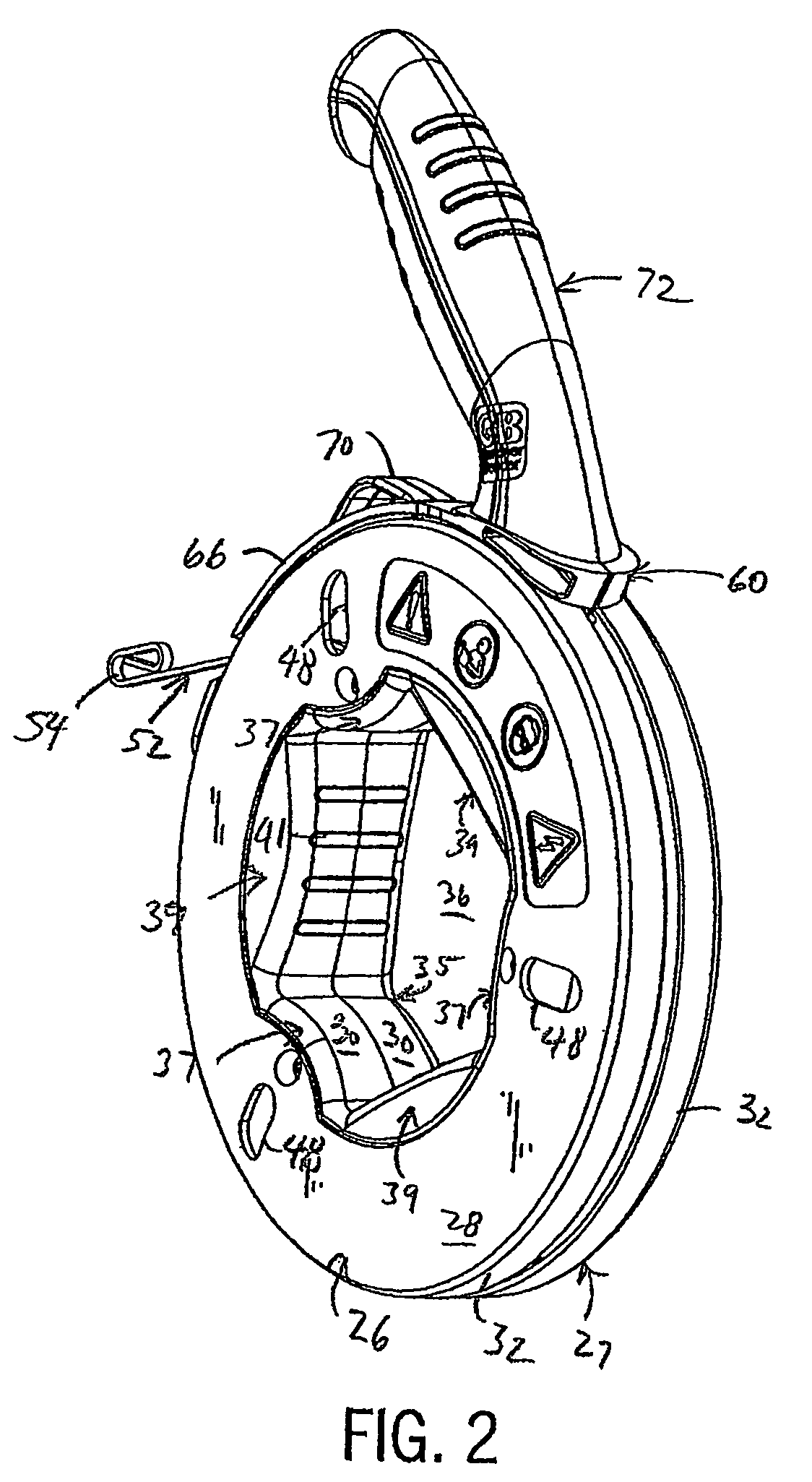
[0037]The drawings referenced herein illustrate a preferred version of a fish tape reel assembly 20. Referring to FIGS. 1-5, the reel assembly 20 includes a reel housing 24 having two annular housing parts 26 and 27 made of a rigid plastic, such as nylon or polypropylene, using any suitable molding technique, such as injection molding. The housing parts 26 and 27 each have a convex annular wall 28 that tapers from an inner peripheral wall 30, configured as discussed in detail below, to a circular outer peripheral wall 32. The housing parts 26 and 27 are concentric about a center axis 34 passing through the middle of a center opening 36 defined by the inner peripheral wall 30. When the housing parts 26 and 27 are joined, the inner peripheral walls 30 define an inner periphery 35 with three convex hand stops 37 spaced equally about the center axis 34 and interposed between three equally spaced convex inner hand grips 39 of a larger radius than the stops 37. Preferably, the inner perip...


PUM


Abstract

A fish tape reel has an ergonomic pistol grip and ergonomic hand grips at an inner periphery of a hollow housing. Fish tape is wound into the housing cavity by rotating the housing with respect to the pistol grip. This can be done manually by grasping the interior handle(s) or using a ratcheted winder that fits into the housing opening and has a lever handle for ratcheting the housing. The reel is held with the housing beneath the pistol grip which has a retainer shoe slidably sandwiched between halves of the housing. The pistol grip is positioned behind a vertical center line of the reel so that the weight of the reel is balanced in a neutral position in which the pistol grip can be grasped with the user's wrist being essentially straight and horizontal. A method of assembling the reel is also disclosed in which the fish tape is attached and wound after the housing is assembled.

Description

CROSS-REFERENCE TO RELATED APPLICATION[0001]This application claims benefit to U.S. Provisional Application No. 60 / 493,819, filed on Aug. 8, 2003.STATEMENT OF FEDERALLY SPONSORED RESEARCH OR DEVELOPMENT[0002]Not applicable.BACKGROUND OF THE INVENTION[0003]1. Technical Field[0004]The present invention relates to fish tapes of the type used by electricians to pull wire through conduit or other spaces, and more particularly to the fish tape reel assembly.[0005]2. Description of the Related Art[0006]A fish tape is a stiff but bendable wire, flexible rod or flat tape typically used to install wire in conduit, through existing walls, or other tight spaces. Because typical electrical wire is very flexible, pushing it through long lengths of conduit is virtually impossible. Pulling wire along the desired path is much more effective. In order to pull the wire, a fish tape, being more rigid than electrical wire, is first pushed along the desired path. Once an end of the fish tape reaches the ...

Claims


Application Information

Patent Timeline
Patent Type & Authority Patents(United States)
IPC IPC(8): H02G1/08H02G11/02
CPCB65H75/406H02G1/085H02G11/02B65H2402/412B65H2701/376
Inventor WIESEMANN, DAVID L.HUEBSCHEN, DAVID A.
Owner POWER PROD
Why Eureka
Try Eureka