Liquid ejecting apparatus

a technology of liquid ejecting apparatus and ejector, which is applied in the direction of power drive mechanism, printing mechanism, printing, etc., can solve the problems of cockring phenomenon that the record sheet is bent, the record sheet is contaminated, and the cockring is not easily generated, so as to achieve the effect of high impact accuracy

Inactive Publication Date: 2008-05-20
SEIKO EPSON CORP
View PDF10 Cites 11 Cited by
  • Summary
  • Abstract
  • Description
  • Claims
  • Application Information

AI Technical Summary

Benefits of technology

[0008]It is therefore an object of the invention to provide a liquid ejecting apparatus which appropriately uses ejecting pulses in accordance with a distance from the nozzle orifice to the target object such that higher impact accuracy can be ensured if the distance is short and a failure due to the mist can be prevented if the distance is long.
[0022]With this configuration, since the liquid droplet ejected by the first pulse selected by the pulse supplier when the distance is the first distance has a relatively high flight speed, it is difficult to generate flight bending and thus it is possible to ensure higher impact accuracy when the distance is the first distance. In addition, since the liquid droplet ejected by the second pulse selected by the pulse supplier when the distance is the second distance has a flight speed slower than that of the liquid droplet ejected by the first pulse, it is difficult to generate a satellite liquid droplet. Thus, when the distance is the second distance, it is possible to suppress mist from being generated and thus to prevent a failure due to the mist.
[0027]In this case, since the liquid droplet ejected by the second pulse has the flight speed slower than that of the liquid droplet ejected by the first pulse and thus the flight time thereof becomes longer, the liquid droplet is impacted at a position which is spaced apart from the ejected position in the movement direction of the liquid ejecting apparatus. On the contrary, since the liquid droplet ejected by the first pulse has the flight speed faster than that of the liquid droplet ejected by the second pulse and the flight time thereof becomes shorter, the liquid droplet is impacted at a position close to just below the ejected position. Accordingly, in the state that the distance is the first distance, when the liquid droplet is ejected by sequentially applying the second pulse and the first pulse to the pressure generator, since the impact positions of the liquid droplets are adjacent to each other, it is possible to form a dot with better accuracy. Moreover, in the state that the distance is the second distance, when the liquid droplet is ejected by sequentially applying the first pulse and the second pulse, since a satellite liquid droplet attached to the liquid droplet ejected by the first pulse is absorbed into the liquid droplet ejected by the second pulse, it is possible to suppress the mist from being generated.

Problems solved by technology

Accordingly, in this kind of printer, when relatively large amount of ink is ejected onto the record sheet, such as full print, a cockring phenomenon that the record sheet is bent by the absorption of the large amount of ink may be caused.
Accordingly, the flight distance of the ink droplet is changed and thus record unevenness is generated or the record sheet contacts the record head and thus the record sheet is contaminated.
Since the record sheet called a dedicated sheet has an ink receiving layer and the ink is absorbed into the ink receiving layer, the cockring is not easily generated.
However, if the paper gap is large, since the flight time for ejecting and impacting the ink droplet becomes longer, the flight bending of the ink droplet is apt to be affected.
As the result, a position in which a dot is formed is deviated from an adequate position and thus image quality is deteriorated.
If the mist floats in the air, the inside of the printer is contaminated.
However, if the flight speed of the ink droplet is suppressed, since the flight time becomes longer while the vicinity of the nozzle orifice is wet or shape unevenness is apt to be affected, the flight bending becomes larger.
As the result, impact accuracy is deteriorated and thus the image quality is deteriorated.
In addition, since the liquid droplet ejected by the second pulse selected by the pulse supplier when the distance is the second distance has a flight speed slower than that of the liquid droplet ejected by the first pulse, it is difficult to generate a satellite liquid droplet.

Method used


Image

  • Liquid ejecting apparatus
  • Liquid ejecting apparatus
  • Liquid ejecting apparatus

Examples


Embodiment Construction

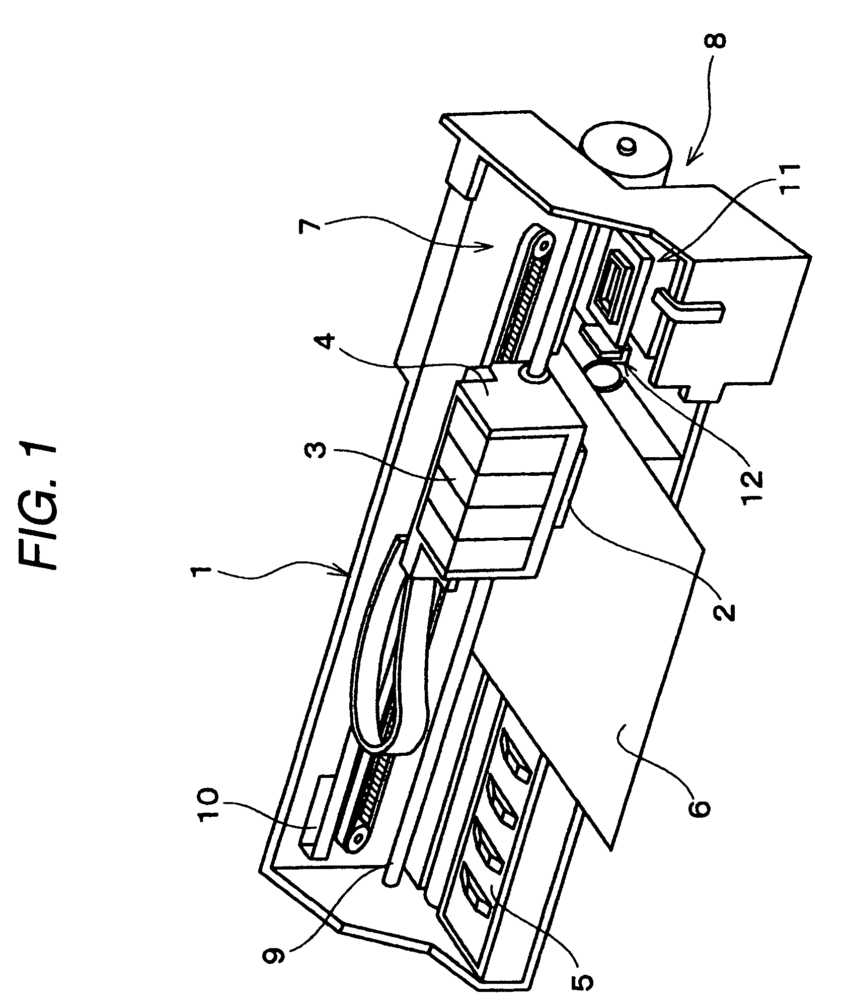
[0039]Hereinafter, an exemplary embodiment according to the present invention will be described with reference to the accompanying drawings. In addition, the below-mentioned embodiment, preferred examples of the present invention are variously defined, but the present invention is not limited to the examples if there is no a description which limits the present invention in the below-mentioned description. Furthermore, hereinafter, an inkjet printer (hereinafter, referred to as printer) illustrated in FIG. 1 is used as a liquid ejecting apparatus of the present invention.

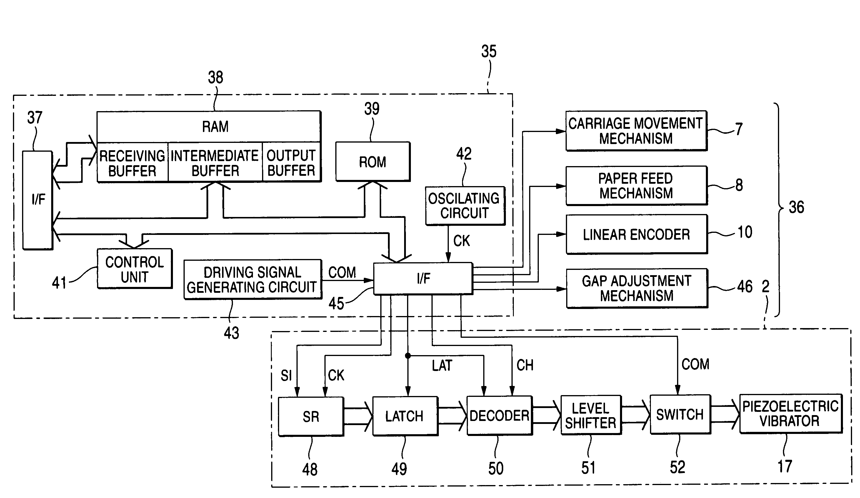
[0040]As shown in FIG. 1, the printer 1 schematically includes a carriage 4 in which a record head 2 can be mounted as a liquid ejecting head and an ink cartridge 3 can be detachably mounted, a platen 5 provided below the record head 2, a carriage movement mechanism 7 which reciprocally moves the carriage 4 (record head 2) in a paper width direction of the record sheet 6 (a kind of target object), that is, a main sc...


PUM


Abstract

A liquid ejecting head includes a nozzle formation face with a nozzle; a pressure chamber communicated with the nozzle; and a pressure generator changing pressure in the chamber so as to eject liquid from the nozzle. An adjuster adjusts a distance between the nozzle formation face and the target medium so as to be at least a first distance, and a second distance that is longer than the first distance. A driving signal generator generates a driving signal that includes a first pulse having at least a first expansion element and a first ejecting element, and a second pulse having at least a second expansion element and a second ejecting element. A pulse supplier selectively supplies a pulse to the pressure generator. The pulse supplier selects the first pulse when the distance is the first distance, and selects the second pulse when the distance is the second distance.

Description

BACKGROUND OF THE INVENTION[0001]The present invention relates to a liquid ejecting apparatus of an inkjet printer and so on, and more particularly, to a liquid ejecting apparatus which drives a pressure generating element using a driving signal including various kinds of ejecting pulses in an ejecting period such that dots having different sizes can be formed on a target object.[0002]A liquid ejecting apparatus includes a liquid ejecting head which can eject liquid as a liquid droplet, and ejects various kinds of liquid from the liquid ejecting head. As a representative example of the liquid ejecting apparatus, there is an image record device of an inkjet printer and so on, which includes, for example, an inkjet record head (hereinafter, referred to as record head) as a liquid ejecting head and ejects / impacts liquid ink as an ink droplet from a nozzle orifice of the record head onto a target object such as a record sheet to form a dot and perform record. In addition, recently, the ...

Claims


Application Information

Patent Timeline
Patent Type & Authority Patents(United States)
IPC IPC(8): B41J25/308B41J2/045B41J29/38
CPCB41J2/04516B41J2/04556B41J2/04581B41J2/04588B41J2/04593B41J2/04596B41J2002/14419
Inventor HOSONO, SATORU
Owner SEIKO EPSON CORP
Why Eureka
Try Eureka