Method for the earthwork of a foundation sunk for a wind energy facility

a technology of wind energy facilities and earthwork, which is applied in the direction of building components, structural elements, bulkheads/piles, etc., can solve the problems of inaccuracy of the anchoring bolt circle, the inability to mount and dismount the anchoring bolt strickle board,

Inactive Publication Date: 2008-05-20
NORDEX ENERGY
View PDF9 Cites 26 Cited by
  • Summary
  • Abstract
  • Description
  • Claims
  • Application Information

AI Technical Summary

Benefits of technology

[0011]In a subsequent step, a reinforcement for the foundation sunk is placed and the anchor cage with reinforcement is poured with concrete. Subsequently, the anchoring bolts are tightened when the tower foot flange is fixed. A particular advantage of the method according to the present invention is that a separate anchoring bolt strickle board is omitted. By doing so, the inaccuracies in the orientation of the bolts created through the use of an anchoring bolt strickle plate are avoided. Further, the operation to mount the separate anchoring bolt strickle plate on the anchor bolts and to remove it thereafter is left out. The present invention is based on the finding that the load distribution plate once set on the anchoring bolts can remain there when it is supported via bolt nuts below the load distribution plate. Upon a predetermined force, the bolt nuts break down, in that the thread of the nuts is stripped off on the thread of the anchoring bolt. The bolt nuts which are strippable in this manner do not hinder the tightening of the anchoring bolt when the tower foot is fixed, so that they have lost their original function.

Problems solved by technology

It has proven to be disadvantageous in the procedure for the earthwork mentioned above that mounting and dismounting of the anchoring bolt strickle board is an expensive operation.
Additionally, inaccuracies in the bores of an anchoring bolt strickle board are created through the reuse thereof, which are maintained when the reinforcement is placed and in the subsequent pouring of concrete, and thus lead to inaccuracies of the anchoring bolt circle.

Method used


Image

  • Method for the earthwork of a foundation sunk for a wind energy facility
  • Method for the earthwork of a foundation sunk for a wind energy facility
  • Method for the earthwork of a foundation sunk for a wind energy facility

Examples


Embodiment Construction

[0019]While this invention may be embodied in many different forms, there are described in detail herein a specific preferred embodiment of the invention. This description is an exemplification of the principles of the invention and is not intended to limit the invention to the particular embodiment illustrated

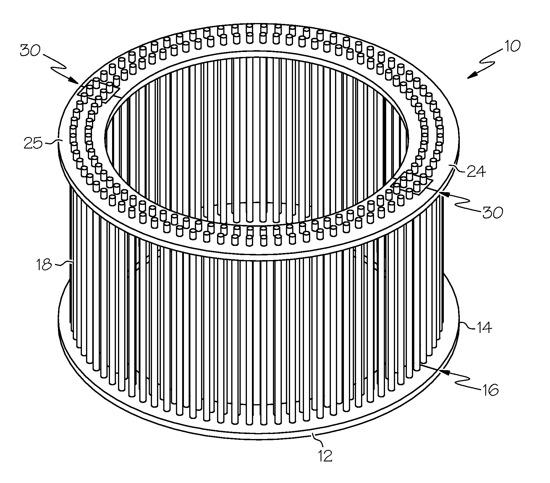
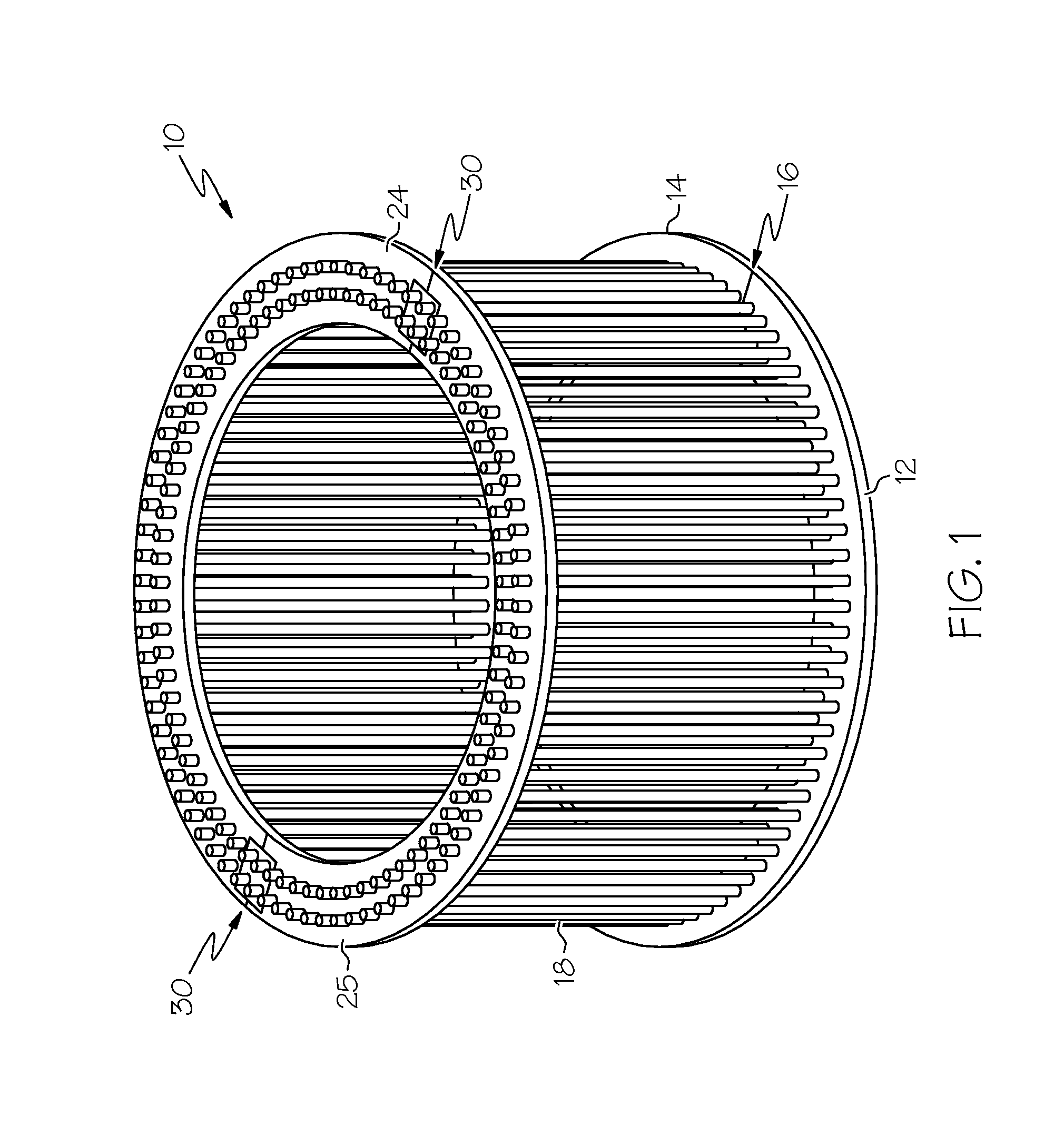
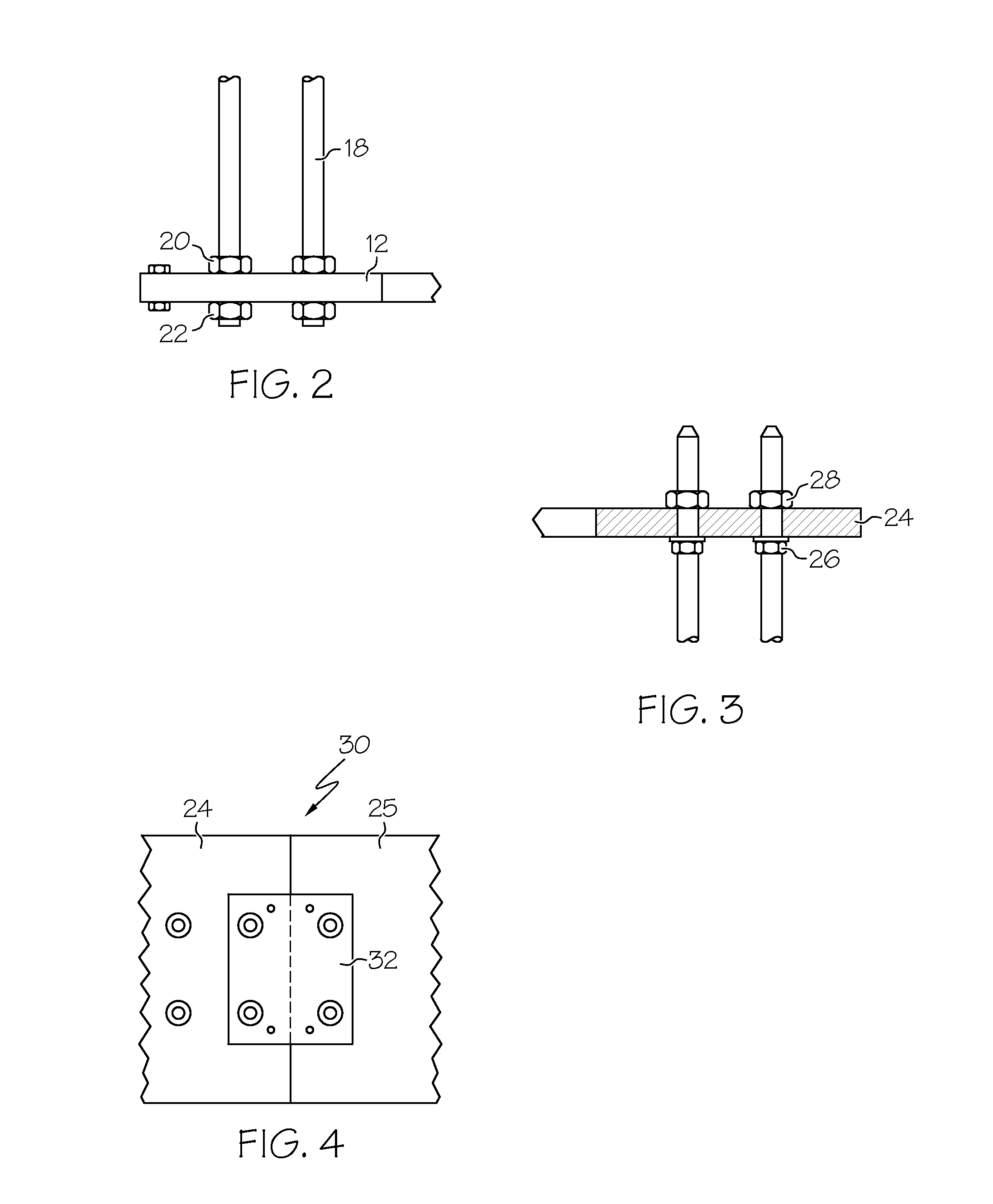
[0020]FIG. 1 shows a ready mounted anchor cage 10 with a two piece anchor plate 12 and 14. Each one of the anchor plates 12 and 14, which abut with each other on an edge 16 in the mounted condition, forms an half circle. (The rear edge is covered in FIG. 1). Anchoring bolts 18 are screwed in the anchor plates 12 and 14. The anchoring bolts are each one fixed on the anchor plate with a pair of nuts 20.

[0021]A load distribution plate 24 is set up on the free ends of the anchoring bolts. As can be recognised in FIG. 3, screw nuts from plastic material 26 are provided below the load distribution plate, which support the load distribution plate 24. The plastic screw nuts 26 functio...


PUM


Abstract

A method for the earthwork of a foundation sunk for a wind energy facility, which has the following steps: an anchor cage is provided, consisting of an anchor plate and several anchoring bolts which are connected with the anchor plate, the free ends of the anchoring bolts are guided through bores in at least one load distribution plate the load distribution plate lays on at least three bolt nuts, which are screwed on the anchoring bolts, a reinforcement for the foundation sunk is mounted and the anchor cage is poured in with the reinforcement, the anchoring bolts protruding with the bolt nuts in this, upon subsequent tightening of the anchoring bolts between anchor plate and load distribution plate, the bolt nuts are stripped over the thread of the anchoring bolt and loose their supporting capability.

Description

CROSS-REFERENCE TO RELATED APPLICATIONS[0001]Not applicable.STATEMENT REGARDING FEDERALLY SPONSORED RESEARCH[0002]Not applicable.BACKGROUND OF THE INVENTION[0003]The present invention is related to a method for the earthwork of a foundation sunk for a wind energy facility.[0004]In principle, two variants are possible for the anchoring of the pipe tower of a wind energy facility. In the first variant, a pipe piece with a circulating flange is set in concrete into a foundation. The tower foot of the wind energy facility is subsequently screwed with the pipe piece. In the second variant, not a pipe piece but an anchor cage, consisting of several anchoring bolts, is set in concrete in the foundation sunk. The tower foot is then screwed together with the anchoring bolts.[0005]In the last mentioned variant, the anchoring bolts are integrated into an anchor cage. The anchor cage has an anchor plate or an anchor ring on its ground, which is screwed together with the anchoring bolts. The fre...

Claims


Application Information

Patent Timeline
Patent Type & Authority Patents(United States)
IPC IPC(8): E02D27/50E02D27/42E02D5/74E04C5/12
CPCE02D27/42E04H12/085F03D11/045F05B2240/90Y02E10/728F03D13/22Y02E10/72
Inventor JAKUBOWSKI, ALEXANDERNITZPON, JOACHIMWEDERHAKE, RALFMARBURGER, MARKUS
Owner NORDEX ENERGY
Why Eureka
Try Eureka