In-situ hydraulic treatment conduit

a hydraulic treatment conduit and conduit technology, applied in the field of environmental remediation systems, can solve the problems of difficult repair of problems, many treatment agents cannot be contained by the bag system, and difficult to ensure the seal about the bag, etc., and achieve the effects of easy scaling up or down in size, large hydraulic pressure, and cost-effective operation and maintenan

Inactive Publication Date: 2008-05-20
TH AGRI & NUTRITION
View PDF15 Cites 0 Cited by
  • Summary
  • Abstract
  • Description
  • Claims
  • Application Information

AI Technical Summary

Benefits of technology

[0002]This invention relates to the field of environment-remediation systems, and in particular to a system and method for controlling the hydraulic gradient between a contained area and a non-contained area to minimize the potential for flow of aqueous matter through non desirable areas of permeable barriers. Of particular note, the invention addresses the option for treatment of fluids that enter the system during movement between the contained area and non-contained area.
[0008]It is an object of this invention to provide a mechanism for controlled flow from containment systems such that uncontrolled flow through the containment structure of contaminated liquids is minimized. It is a further object of this invention to provide a flow option for containment systems that is cost-effective to operate and maintain.
[0009]These objects, and others, are achieved by providing a system that serves to control the hydraulic gradient between the area within a containment system and the area outside the containment system, coupled with an option of treating contaminated fluids. Preferably, the treatment system includes a large conduit between the inside-area and the outside-area that is accessible via a manhole. This conduit can be filled with materials for the treatment of groundwater, the manhole-sized access providing a relatively easy means of providing and replacing this material. Because the conduit design can easily be scaled up or down in size as appropriate for a given hydrogeologic setting, large hydraulic pressures on either side of the open conduit can be expected to be substantially equal. Gates and screens are provided on either side of the conduit, to facilitate flow control, with manhole accessways to facilitate maintenance of these gates and screens.BRIEF DESCRIPTION OF THE DRAWINGS

Problems solved by technology

Although the use of permeable bags for containing the remediation material 150 facilitates replacement of the material 150, it may be difficult to assure a “seal” about the bags to prevent contaminated materials from entering the well 140 and migrating around the bags through preferential pathways.
Additionally, many treatment agents cannot be contained by a bag system.
Should contaminants or formation materials enter the well 140, or other problems develop in the well 140, it will be difficult to repair the problem, and, in all likelihood, a costly installation of a new well 140 and pipe 145 may be required.
It has been found that a substantial difference in hydraulic pressure between the inside-area and the outside-area is likely to cause some flow of the water between the areas, via the bedrock 120 and other less-than-perfect seals between the inside-area and outside-area.
Such a system will not necessarily have a significant impact on equalizing the hydraulic pressures between the inside-area and the outside-area, and the likelihood of contaminated water passing from the inside-area to the outside-area in an uncontrolled fashion remains.

Method used


Image

  • In-situ hydraulic treatment conduit
  • In-situ hydraulic treatment conduit

Examples


Embodiment Construction

[0014]In the following description, for purposes of explanation rather than limitation, specific details are set forth such as the particular architecture, interfaces, techniques, etc., in order to provide a thorough understanding of the present invention. However, it will be apparent to those skilled in the art that the present invention may be practiced in other embodiments, which depart from these specific details. For purposes of simplicity and clarity, detailed descriptions of well-known components and methods are omitted so as not to obscure the description of the present invention with unnecessary detail.

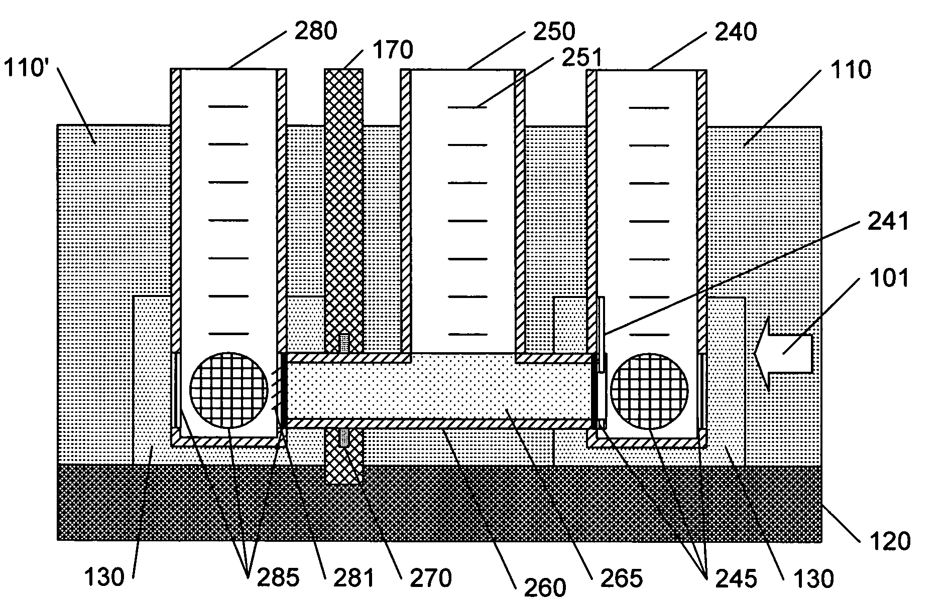
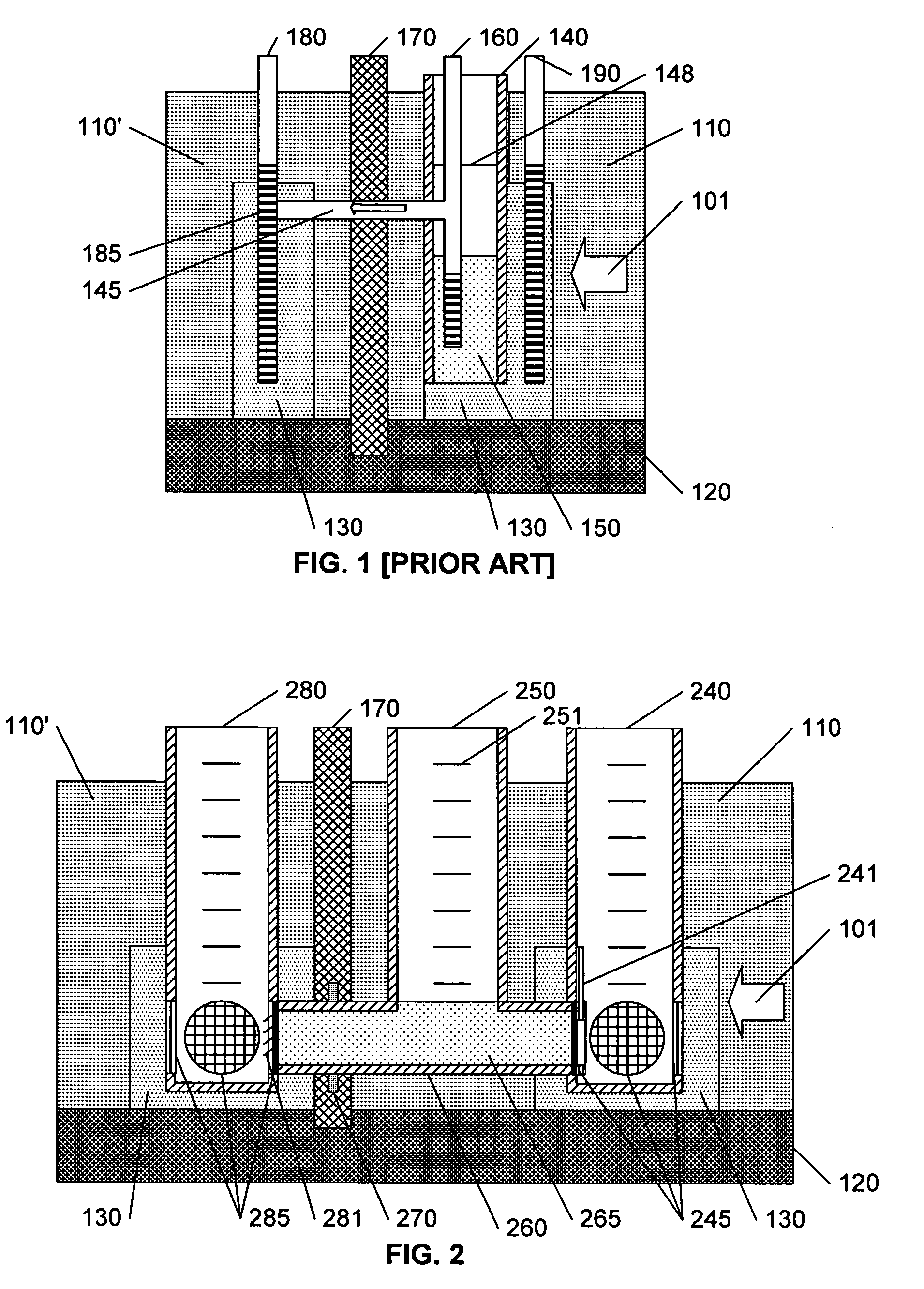
[0015]The invention is premised on the observation that control of the gradient of hydraulic pressures between a contained area and an outside-area will have a significant impact of the effectiveness of a containment system. To this end, FIG. 2 illustrates an example hydraulic treatment conduit in accordance with this invention.

[0016]In FIG. 2, a conduit 260 with a diameter s...


PUM

PropertyMeasurementUnit
diameteraaaaaaaaaa
diameteraaaaaaaaaa
diameteraaaaaaaaaa

Abstract

A system is installed in the subsurface to control the hydraulic gradient between the area within a containment system and the area outside the containment system, and provides an easy-to-maintain treatment system. Preferably, the treatment system includes a sufficiently sized conduit between the inside-area and the outside-area that is accessible via a manhole. This conduit can be filled with remedial material or other treatment equipment, the manhole-sized access providing a relatively easy means of providing, maintaining, and replacing this material and equipment. Because the conduit is appropriately sized, hydraulic pressures on either side of the open conduit can be expected to be substantially equal, thereby reducing the potential of leakage of contaminants caused by hydrostatic pressure. Gates and screens are provided on either side of the conduit, to facilitate flow control, with manhole accessways to facilitate maintenance of these gates and screens.

Description

[0001]This application claims the benefit of U.S. Provisional Patent Application 60 / 645,403, filed 19 Jan. 2005.BACKGROUND AND SUMMARY OF THE INVENTION[0002]This invention relates to the field of environment-remediation systems, and in particular to a system and method for controlling the hydraulic gradient between a contained area and a non-contained area to minimize the potential for flow of aqueous matter through non desirable areas of permeable barriers. Of particular note, the invention addresses the option for treatment of fluids that enter the system during movement between the contained area and non-contained area.[0003]The containment of environmental contaminants in groundwater is an area of ongoing concern. When contaminants are found in environmental media such as soil or groundwater, efforts are often undertaken to prevent an expansion of the contaminated area. In severe contamination cases, containment structures are used to restrict the flow of contaminants and ground...

Claims


Application Information

Patent Timeline
Patent Type & Authority Patents(United States)
IPC IPC(8): C02F1/00
CPCB09C1/002C02F2103/06
Inventor CLEARY, JOHN P.
Owner TH AGRI & NUTRITION
Why Eureka
Try Eureka