Optical unit and image pickup apparatus having the same
a pickup apparatus and optical unit technology, applied in the field of optical unit and image pickup apparatus having the same, can solve the problems of inability to achieve thin apparatus, easy shaking of camera, and inconvenient minimizing of the body of the apparatus, so as to achieve the effect of reducing the size of the apparatus
- Summary
- Abstract
- Description
- Claims
- Application Information
AI Technical Summary
Benefits of technology
Problems solved by technology
Method used
Image
Examples
first embodiment
THE FIRST EMBODIMENT
[0035]The first embodiment of the present invention will be described below.
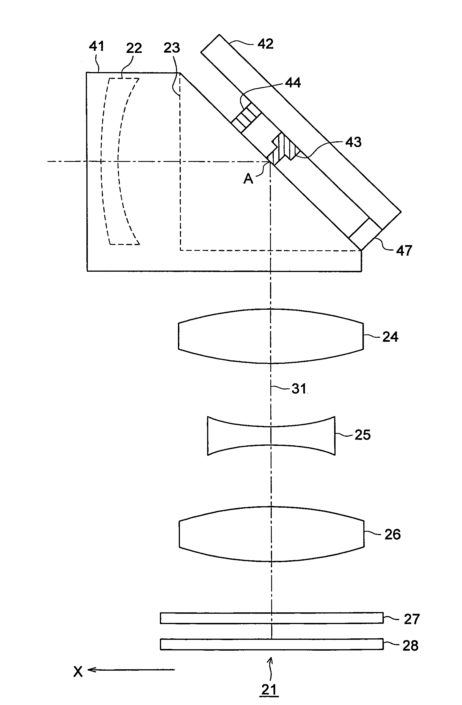
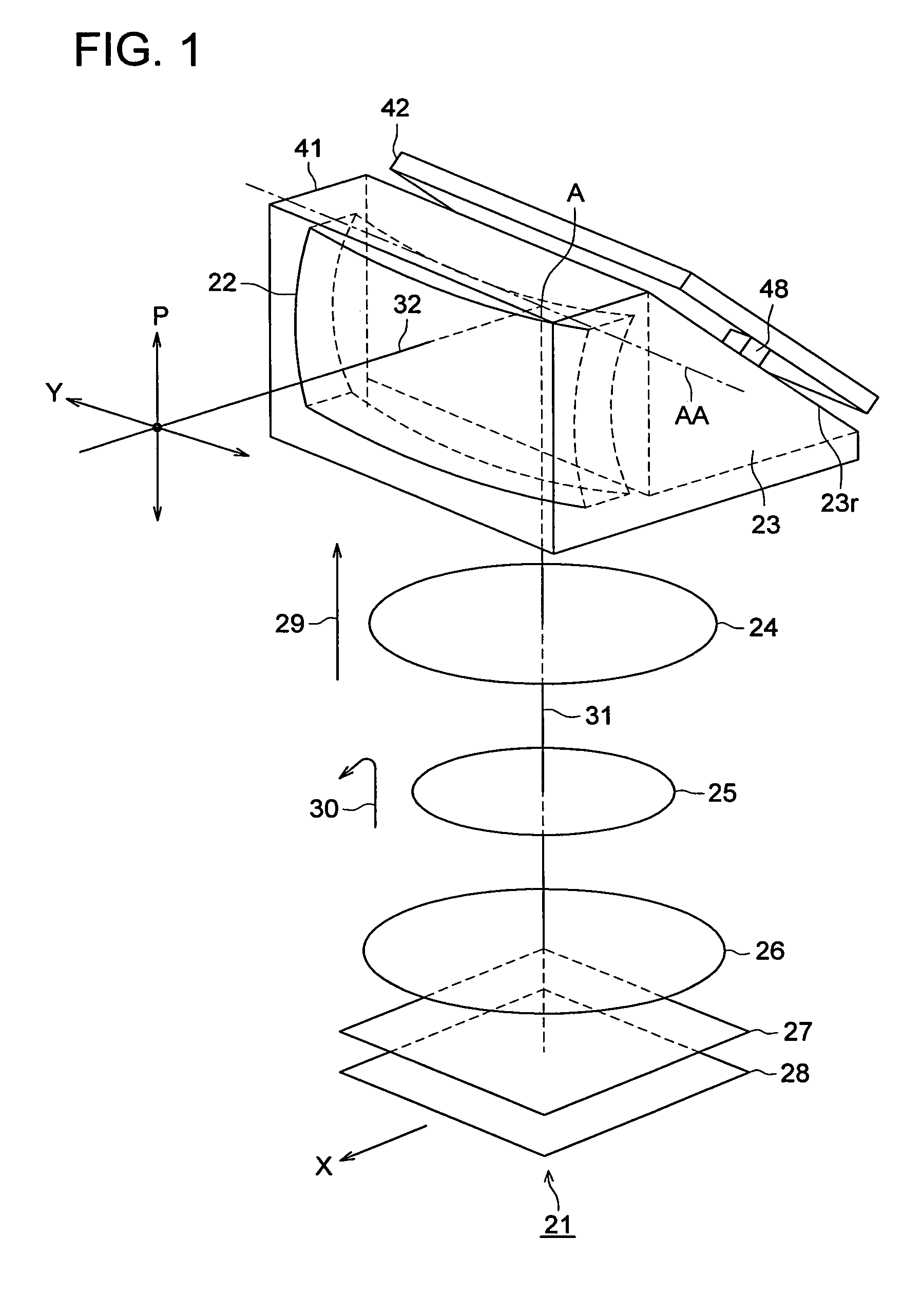
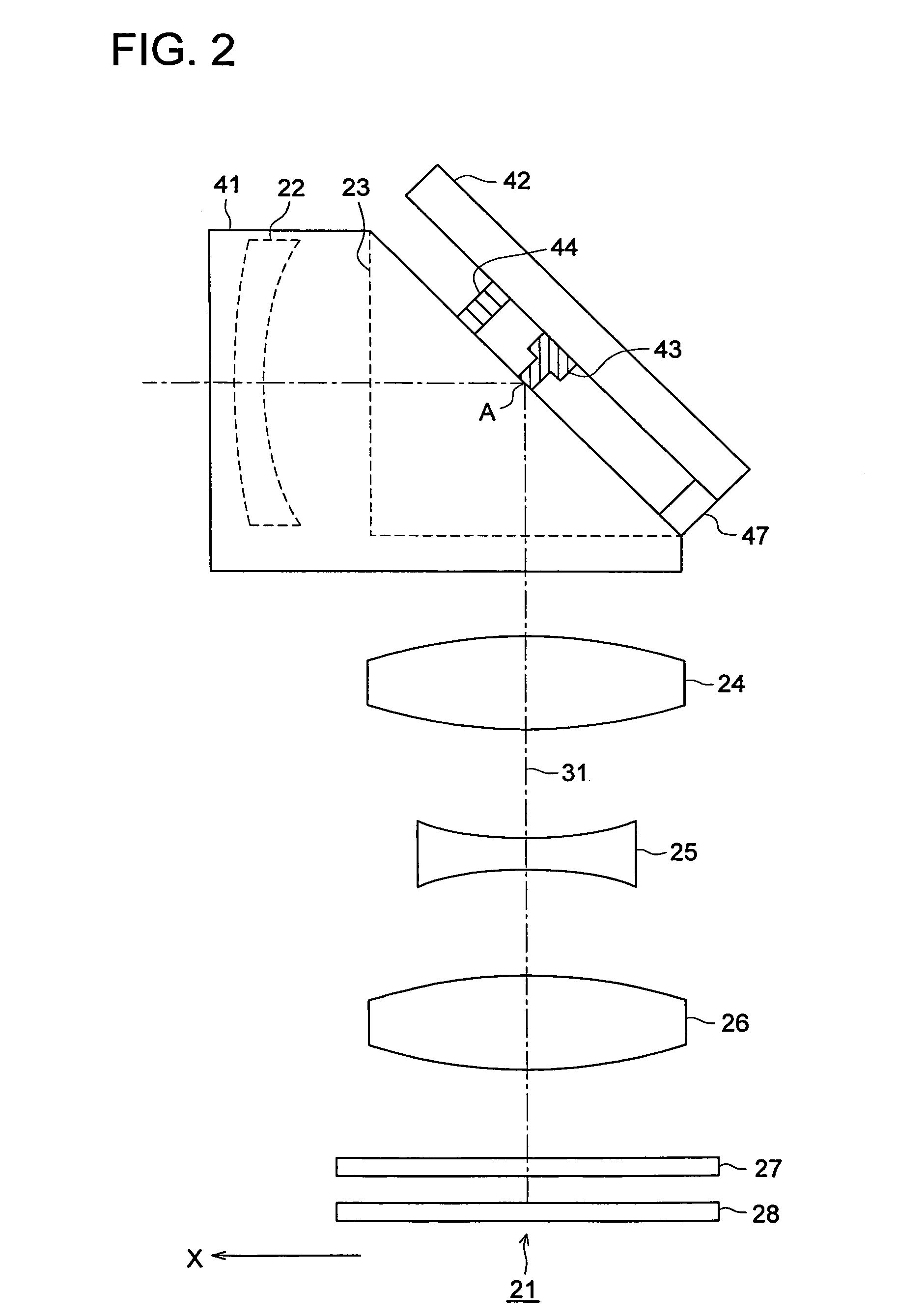
[0036]FIG. 1 illustrates a perspective view of an optical unit 21. In FIG. 1, a symbol 22 denotes the first lens group; a symbol 23 denotes a prism being a reflection member; a symbol 24 denotes the second lens group; a symbol 25 denotes the third lens group; a symbol 26 denotes the fourth lens group; a symbol 27 denotes a low pass filter; and a symbol 28 denotes an image pickup element. The first lens group 22 forms a front lens group positioned in an object side against the reflection member. The second lens group 24, the third lens group 25, the fourth lens group 26 form a rear lens group positioned in an image forming side against the reflection member. A symbol 32 denotes an optical axis of the front lens group and a symbol 31 denotes an optical axis of the rear lens group. The optical axis 32 and the optical axis 31 cross to a reflection surface 23r of the prism 32 at a point A. A s...
second embodiment
THE SECOND EMBODIMENT
[0080]The difference between the first and the second embodiment is that the front lens group and the prism in the second embodiment differently move while the first lens group and the prism are driven in one body in the first embodiment. Further, in response to the moving by angle “a” in the P-direction of the prism, the driving angle of the front lens is going to be angle “2 a” in the second embodiment.
[0081]The second embodiment of the present invention will be described below.
[0082]FIG. 9 illustrates a configuration of an optical unit 111 of the embodiment. In FIG. 9, the optical unit 111 employs the same optical design as the first embodiment. The same element having the same functionality as the element shown in FIG. 4 has the same numeral and the explanation will be eliminated. In FIG. 9, a symbol 112 is the case of the first lens group, which includes the first lens group 22. Rack gears 113a and 133b (not shown) are formed on a part of surface of the fir...
third embodiment
THE THIRD EMBODIMENT
[0096]The third embodiment of the present invention will be described by referring to drawings.
[0097]In the first and second embodiments, a single lens configures the front lens group located in the optical object side of the reflection member. In the third embodiment, a plurality of lens groups configures the front lens groups.
[0098]FIG. 12 illustrates the configuration of an optical unit 131 of the third embodiment. A symbol 132 denotes the first lens group; a symbol 133 denotes the second lens group; a symbol 134 denotes the third lens group; and a symbol 135 denotes a reflection mirror being a reflection member for inflecting the optical axis of the optical axis. A symbol 136 denotes the forth lens group; a symbol 137 denotes the fifth lens group; a symbol 138 denotes a low pass filter; and a symbol 139 denotes an image pickup element. The first lens group—the third lens group configures a front lens group, which is located in the object side in respect to th...
PUM
 Abstract
Description
Claims
Application Information
 - R&D
- Intellectual Property
- Life Sciences
- Materials
- Tech Scout
- Unparalleled Data Quality
- Higher Quality Content
- 60% Fewer Hallucinations
Browse by: Latest US Patents, China's latest patents, Technical Efficacy Thesaurus, Application Domain, Technology Topic, Popular Technical Reports.
© 2025 PatSnap. All rights reserved.Legal|Privacy policy|Modern Slavery Act Transparency Statement|Sitemap|About US| Contact US: help@patsnap.com


