Apparatus for power transmission

a technology of power transmission apparatus and power transmission circuit, which is applied in the direction of electrical equipment, power conversion systems, electric generator control, etc., can solve the problems of laborious blade angle adjustment, inability to precisely adjust the rotational speed, and the above-described circuit has the disadvantage of requiring a large network inductor and a large d.c. capacitor, and complex inverter bridge control logic. to achieve the effect of suppressing overvoltag

Inactive Publication Date: 2005-06-28
RICOTEC
View PDF15 Cites 4 Cited by
  • Summary
  • Abstract
  • Description
  • Claims
  • Application Information

AI Technical Summary

Benefits of technology

[0018]Thus, a situation is reached where both a large-capacitance d.c. capacitor functioning as an energy storage and a high-inductance current-limiting inductor are superfluous. In practice, it may be necessary to use a low-capacitance d.c. capacit

Problems solved by technology

Thus, a drawback with such an arrangement is this very need for precise adjustment of rotational speed, which e.g. in wind power stations requires laborious adjustment of the blade angle.
Thus, the above-described circuit has the disadvantage of requiring a large d.c. capacitor and a large network inductor as well as a complex inverter bridge control logic.
The voltage produced by th

Method used


Image

  • Apparatus for power transmission
  • Apparatus for power transmission
  • Apparatus for power transmission

Examples


Embodiment Construction

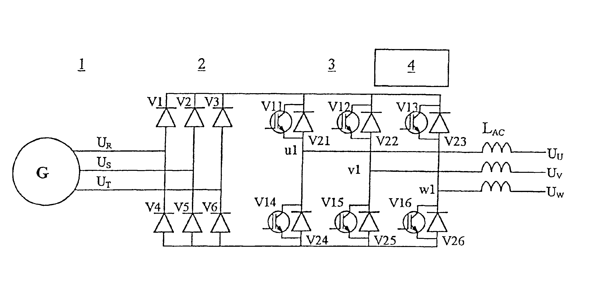
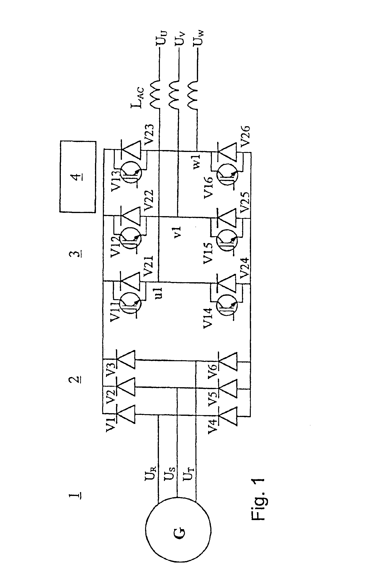
[0026]FIG. 1 presents a three-phase alternating-current generator 1 and a control apparatus connected to it, through which the three-phase alternating current (phase voltages UR, US, UT) supplied by the generator is passed into a three-phase electric network (phase voltages UU, UV, UW) having a constant frequency, e.g.: 50 Hz.

[0027]The control apparatus comprises a non-controlled full-wave rectifier bridge 2 for rectifying the three-phase alternating current supplied by the generator 1 and feeding it into the d.c. intermediate circuit, and a controlled inverter bridge 3, connected to it directly without a high-capacitance capacitor unit smoothing the direct current of the intermediate circuit, for passing the current of the d.c. intermediate circuit into a three-phase alternating-voltage network. The semiconductor switches of the inverter bridge are controlled by a control unit 4.

[0028]The rectifier bridge 2 consists of diodes V1-V6, and the inverter bridge 3 consists of fully gate-...


PUM


Abstract

Apparatus for the transfer of electric power produced by at least one multi-phase alternating-current generator (1) or generator unit into at least one multi-phase alternating-current power network (Uu,Uv,Uw), said apparatus comprising at least one control unit (4), at least one non-controlled rectifier bridge (2), a direct-current intermediate circuit and at least one controlled inverter bridge (3) for supplying d.c. power into an alternating-current power network, said inverter bridge (3) having fully gate-controlled semiconductor switches (V11-V16) in its upper and lower branches, and said control unit controlling the semiconductor switches (V11-V16) of the inverter bridge (3) so as to cause them to conduct in such manner that: —in the upper branch, the switch in each phase conducts substantially as long as the instantaneous value of the network phase voltage (Uu,Uv,Uw) in question is the most positive, and —in the lower branch, correspondingly the switch in each phase conducts substantially as long as the instantaneous value of the network phase voltage (Uu,Uv,Uw) in question is the most negative. The rectifier bridge (2) is connected directly to the inverter bridge (3) without a d.c. capacitor unit functioning as an intermediate energy storage. In addition, the direct current output from the rectifier bridge (2) is conducted directly into those two a.c. network phases in which the magnitudes of the instantaneous values of the voltages are highest, without current limitation by an inductor unit.

Description

[0001]This application is the national phase under 35 U.S.C. §371 of PCT International Application No. PCT / FI02 / 00077 which has an International filing date of Feb. 1, 2002, which designated the United States of America.BACKGROUND OF THE INVENTION[0002]Field of the Invention[0003]The present invention relates to an apparatus for the transmission of electric power produced by a multi-phase alternating current generator to a multi-phase alternating-current power network, said apparatus comprising a control unit, a non-controlled rectifier bridge, a direct-current intermediate circuit and a controlled inverter bridge for supplying direct-current power into the alternating-current power network.[0004]Description of Background Art[0005]In the production of electric power, e.g. in hydropower and wind power stations, synchronous generators are generally used for the conversion of mechanical energy into electric energy. When a synchronous generator is connected directly to an electric power...

Claims


Application Information

Patent Timeline
IPC IPC(8): H02M5/458H02M5/00
CPCH02M5/458
Inventor SALAMA, MIKKO
Owner RICOTEC
Why Eureka
Try Eureka