Zoom lens and imaging apparatus
A zoom lens, image-side technology, used in image communication, television, optics, etc., can solve the problems of increased aberration, obvious off-axis aberration, etc., and achieve the effect of size suppression, large image circle, and good optical performance
- Summary
- Abstract
- Description
- Claims
- Application Information
AI Technical Summary
Problems solved by technology
Method used
Image
Examples
Embodiment 1
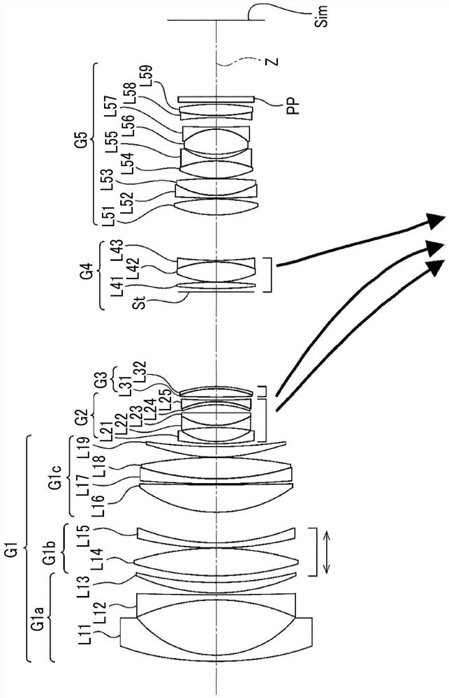
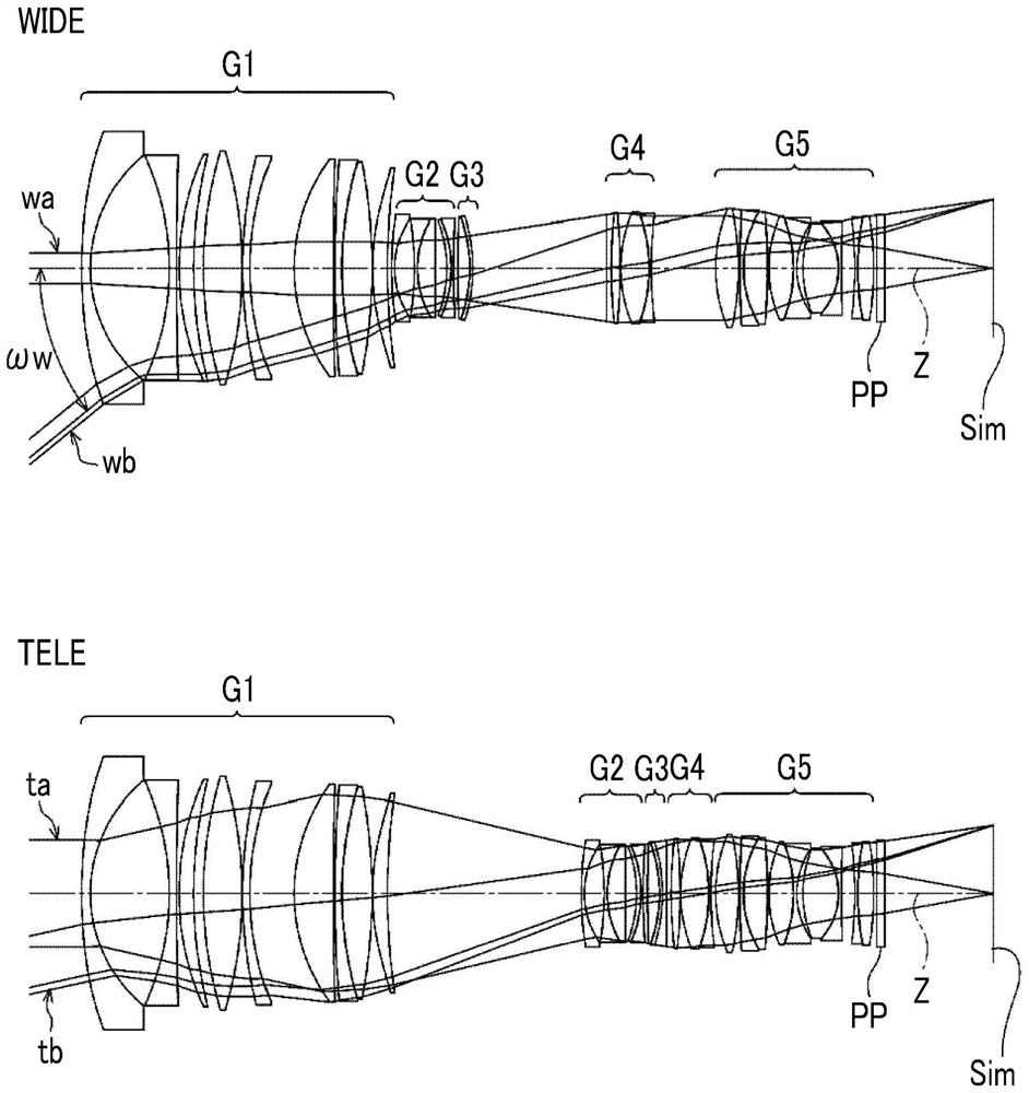
[0085] The structure of the zoom lens of embodiment 1 and the moving track are shown in figure 1 , and its illustration method and structure are as described above, so a part of repeated description is omitted here. The zoom lens of Embodiment 1 includes a first lens group G1 having positive refractive power, a second lens group G2 having negative refractive power, a third lens group G3 having positive refractive power, and a fourth lens group G3 having positive refractive power in order from the object side to the image side. Lens group G4 and a fifth lens group G5 with positive refractive power. When zooming, the first lens group G1 and the fifth lens group G5 are fixed relative to the image plane Sim, and the second lens group G2, the third lens group G3, and the fourth lens group G4 change the distance between adjacent lens groups. Move along the optical axis Z at intervals. The first lens group G1 includes a 1a lens group G1a having a negative refractive power, a 1b len...
Embodiment 2
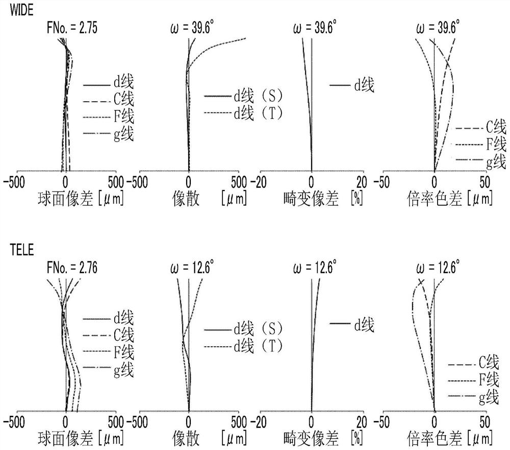
[0114] The structure and moving track of the zoom lens of embodiment 2 are shown in Figure 4 . The zoom lens of Example 2 has the same configuration as that of the zoom lens of Example 1 in outline. Regarding the zoom lens of Example 2, the basic lens data are shown in Table 4A and Table 4B, the specifications and variable surface spacing are shown in Table 5, the aspheric coefficients are shown in Table 6, and the aberration diagrams are shown in Figure 5 .
[0115] [Table 4A]
[0116] Example 2
[0117] sn R D Nd vd θgF *1 171.58622 2.900 1.77250 49.60 0.55212 2 48.60432 26.868 3 -92.24749 2.399 1.55032 75.50 0.54001 4 794.16247 0.539 5 88.58331 4.900 1.53996 59.46 0.54418 6 142.91667 2.952 7 140.06699 13.625 1.43700 95.10 0.53364 8 -129.48065 0.125 9 155.09605 2.399 1.84666 23.78 0.61923 10 99.11860 13.898 11 62.26591 13.052 1.43700 95.10 ...
Embodiment 3
[0129] The structure and moving track of the zoom lens of embodiment 3 are shown in Figure 6 . The zoom lens of Example 3 has the same configuration as that of the zoom lens of Example 1 in outline. Regarding the zoom lens of Example 3, the basic lens data are shown in Table 7A and Table 7B, the specifications and variable surface spacing are shown in Table 8, the aspheric coefficients are shown in Table 9, and the aberration diagrams are shown in Figure 7 .
[0130] [Table 7A]
[0131] Example 3
[0132] sn R D Nd vd θgF *1 191.78045 2.900 1.77250 49.60 0.55212 2 49.74501 26.241 3 -92.58733 2.400 1.61800 63.33 0.54414 4 -1130.51571 0.528 5 106.37599 4.460 1.56732 42.84 0.57814 6 179.15187 2.842 7 163.36873 12.490 1.43700 95.10 0.53364 8 -137.01357 0.130 9 173.88007 2.460 1.84666 23.78 0.61923 10 111.63652 14.847 11 62.88399 13.780 1.43700 95....
PUM
 Abstract
Description
Claims
Application Information
 - R&D
- Intellectual Property
- Life Sciences
- Materials
- Tech Scout
- Unparalleled Data Quality
- Higher Quality Content
- 60% Fewer Hallucinations
Browse by: Latest US Patents, China's latest patents, Technical Efficacy Thesaurus, Application Domain, Technology Topic, Popular Technical Reports.
© 2025 PatSnap. All rights reserved.Legal|Privacy policy|Modern Slavery Act Transparency Statement|Sitemap|About US| Contact US: help@patsnap.com


