Method of self-servo writing in a disk drive using multiple timing windows

a disk drive and timing window technology, applied in the field of disk drives, can solve the problems of rework or scrapping, increase the self-servo writing time,

Inactive Publication Date: 2008-05-20
SEAGATE TECH HDD HLDG +3
View PDF16 Cites 84 Cited by
  • Summary
  • Abstract
  • Description
  • Claims
  • Application Information

AI Technical Summary

Problems solved by technology

If the disk drive fails the self-scan tests, it is either reworked or scrapped at this late manufacturing stage.
However, the second pass substantially increases the self-servo writing time.

Method used


Image

  • Method of self-servo writing in a disk drive using multiple timing windows
  • Method of self-servo writing in a disk drive using multiple timing windows
  • Method of self-servo writing in a disk drive using multiple timing windows

Examples


Embodiment Construction

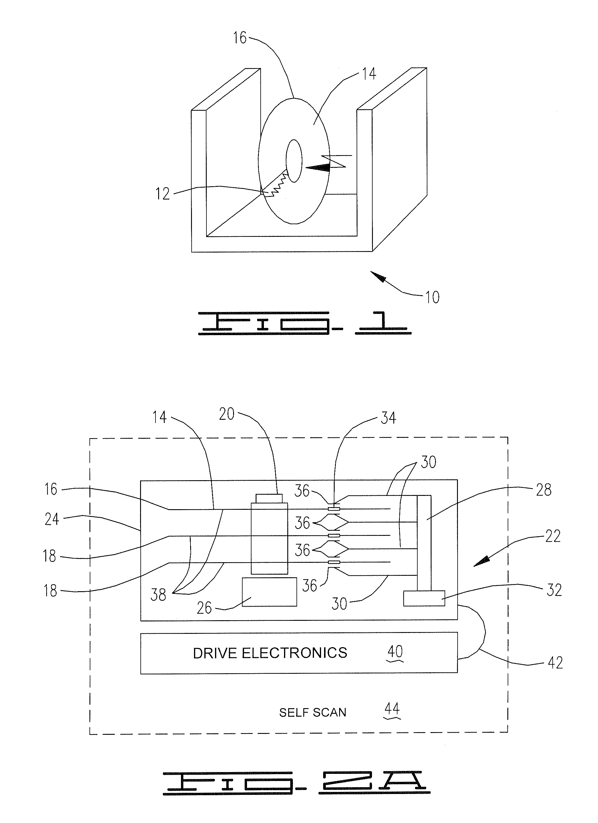
[0027]FIG. 1 shows a printing station 10 that writes a reference pattern 12 to a disk surface 14 of a magnetic reference disk 16.

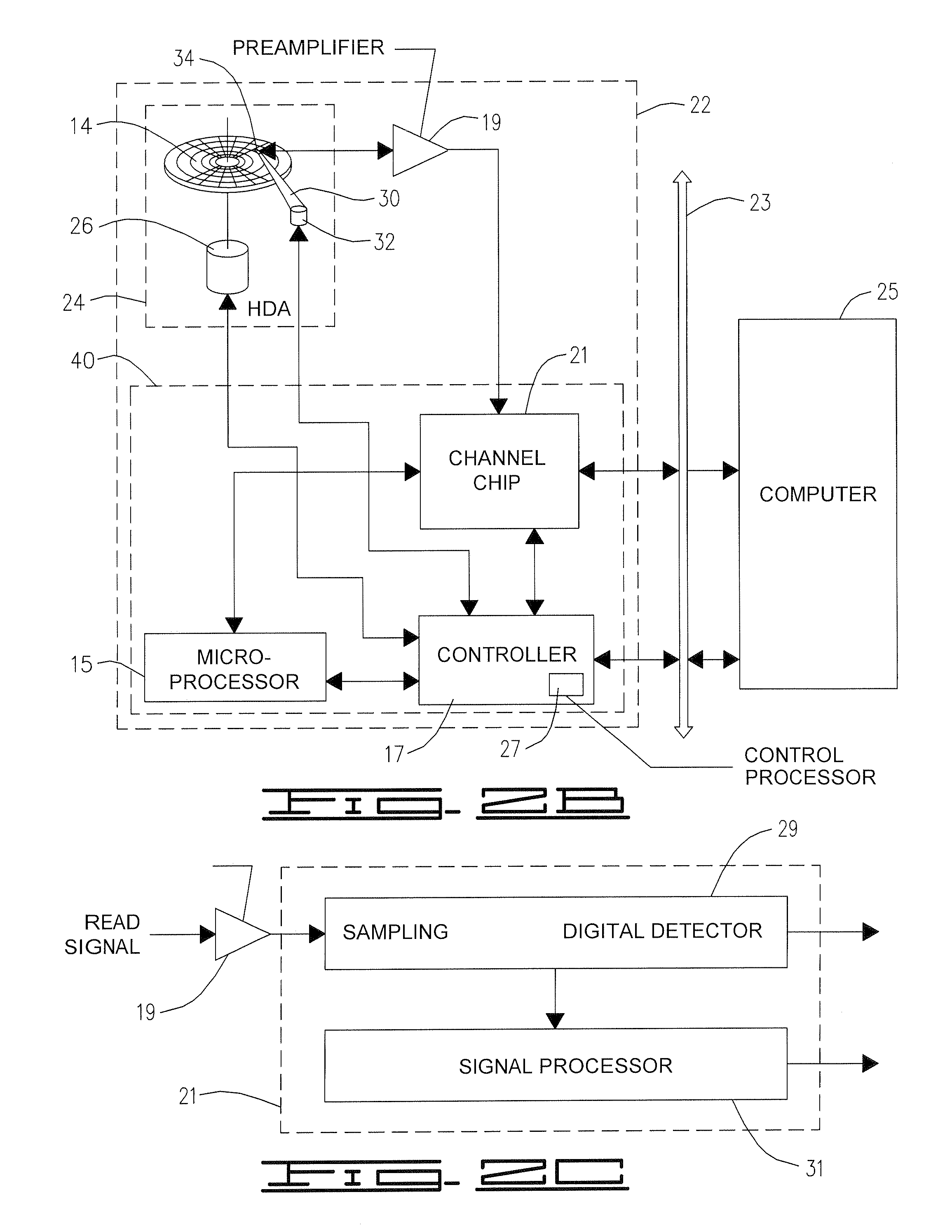
[0028]FIG. 2A shows the reference disk 16 and other disks 18 assembled on a spindle 20 of a disk drive 22 being assembled. The spindle 20 is mounted within a head-disk assembly (HDA) 24 and is rotated at a predetermined angular velocity by a spindle motor 26. A comb-like actuator assembly 28 is included in the HDA 24. The actuator assembly 28 includes head arms 30 rotated by a voice coil motor (VCM) 32 to position the transducer heads 34 and 36 adjacent to the disk surface 14 of the reference disk 16 and to the disk surfaces 38 of the disks 16 and 18. The disk surface 14 is the top surface of the reference disk 16, and the disk surfaces 38 are the bottom surface of the reference disk 16 and the top and bottom surfaces of the disks 18. The disk surface 14 includes the reference pattern 12 and the disk surfaces 38 are blank at this stage. Thus, the disks 18 ...


PUM

PropertyMeasurementUnit
shapeaaaaaaaaaa
densityaaaaaaaaaa
areasaaaaaaaaaa

Abstract

A disk drive includes a head and a disk, spiral patterns are located on the disk, and the disk drive self-writes servo patterns on the disk using the spiral patterns as a reference for servoing the head. In an embodiment, the disk drive uses preliminary servo patterns to determine repeatable runout of the spiral patterns. In another embodiment, the disk drive reads each spiral pattern with multiple timing windows.

Description

CROSS-REFERENCE TO RELATED APPLICATIONS[0001]This application is a divisional of U.S. application Ser. No. 10 / 128,959 filed on Apr. 23, 2002 now U.S. Pat. No. 7,088,533.FIELD OF THE INVENTION[0002]The present invention relates to disk drives, and more particularly to disk drive self-servo writing.BACKGROUND OF THE INVENTION[0003]In many processing and computing systems, magnetic data storage devices such as disk drives are used for storing data. A typical disk drive includes a spindle motor for rotating one or more data storage disks having data storage surfaces, a head arm that supports one or more transducer heads, and an actuator for moving the heads radially across the disks to enable the heads to read from and write to concentric tracks on the disks.[0004]In general, the head is positioned very close to the corresponding disk surface. Typical clearance between the head and a smooth disk surface is about one microinch, or less. The close proximity of the head to the disk allows ...

Claims


Application Information

Patent Timeline
Patent Type & Authority Patents(United States)
IPC IPC(8): G11B5/596
CPCB82Y10/00G11B5/59661G11B5/59666G11B5/59688G11B5/743
Inventor SHEPHERD, STANHAYS, NATHAN J.
Owner SEAGATE TECH HDD HLDG
Why Eureka
Try Eureka