Printing in different modes according to image size

a printing mode and image size technology, applied in the field of dots, can solve the problems of large waste of printing paper area, and achieve the effects of rapid printing, small average feed, and large average feed

Inactive Publication Date: 2008-05-27
SEIKO EPSON CORP
View PDF11 Cites 3 Cited by
  • Summary
  • Abstract
  • Description
  • Claims
  • Application Information

AI Technical Summary

Benefits of technology

[0011]With such a printer, a printing mode may be selected; and an image may be printed according to the selected mode. In the printing of the image, main scanning may be executed by moving at least one of a dot printing head and a print medium, and sub-scanning may be executed by moving the print medium in a direction perpendicular to a direction of the main scanning between the main scannings. In the selecting a printing mode, one of a first printing mode and a second printing mode may be selected. The first printing mode is preferably the printing mode wherein, when a relatively large image in a direction of the sub-scanning is to be printed, a relatively large number of dot-forming elements are used to form dots and a sub-scanning with a relatively large average feed are executed. The second printing mode is preferably the printing mode wherein, when a relatively small image in the direction of the sub-scanning is to be printed, a relatively small number of dot-forming elements are used to form dots and a sub-scanning with a relatively small average feed are executed. Such an embodiment allows large images to be rapidly printed and smaller images to be more efficiently printed on printing paper.
[0012]Printing in the second printing mode is particularly effective for when relatively small images are printed multiple times at varying positions in the sub-scanning direction on the same print medium. Printing in the second printing mode is thus effective, for example, when the print medium is a roll of paper.
[0013]In another embodiment, the sub-scanning may be executed with a relatively large fixed first feed in the first printing mode; and the sub-scanning may be executed with a relatively low fixed second feed in the second printing mode. Such an embodiment allows printing to be done with a simple process.

Problems solved by technology

Thus, in the case of smaller printed images, the images are not printed proportionately to the surface area of the printing paper that can be used to print the images, resulting in a greater waste of printing paper area.

Method used


Image

  • Printing in different modes according to image size
  • Printing in different modes according to image size
  • Printing in different modes according to image size

Examples


first example

A. FIRST EXAMPLE

A1. Device Structure

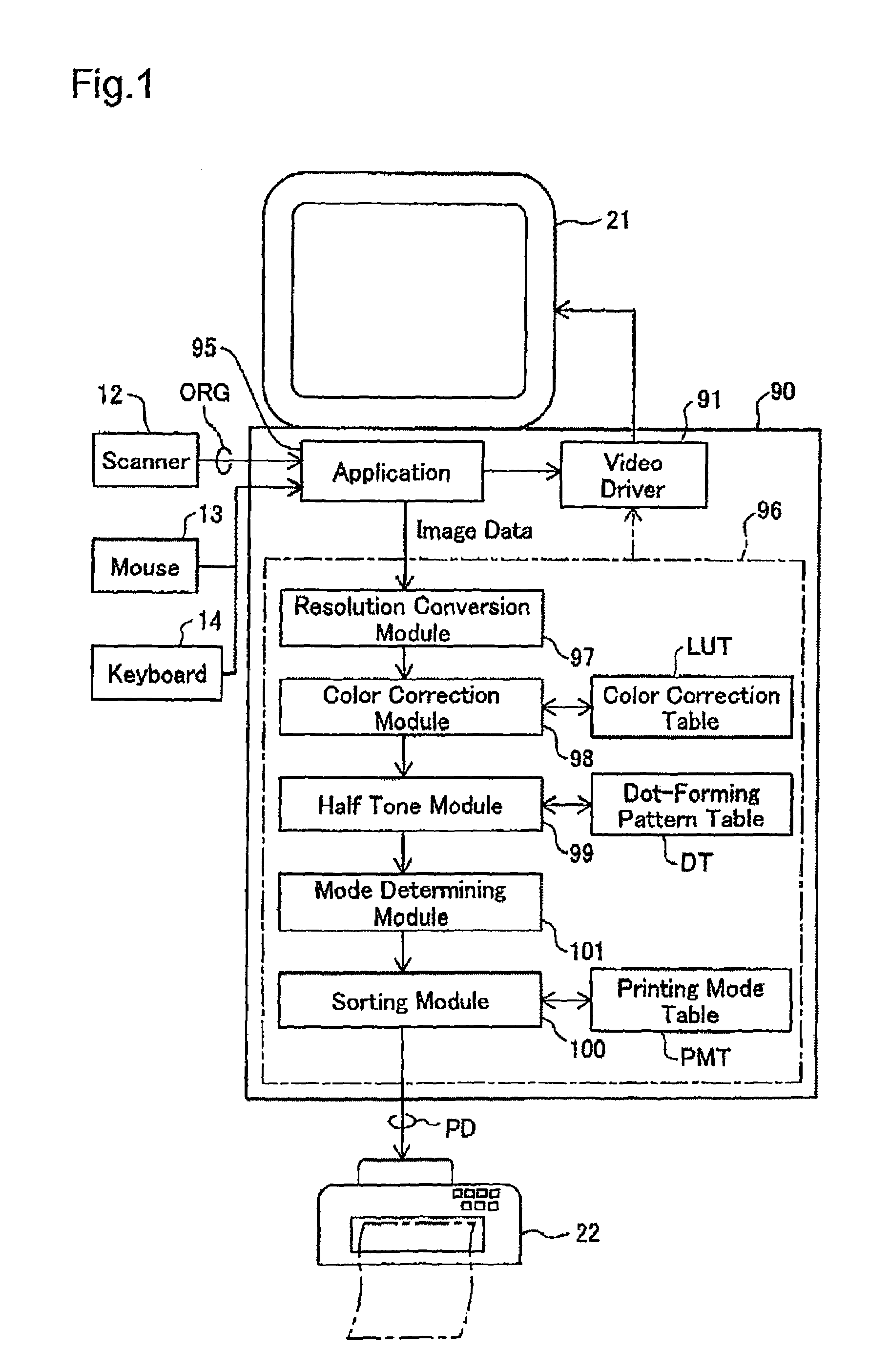
[0043]FIG. 1 is a block diagram of the structure of the software for a printing device according to an embodiment of the invention. This printing system is furnished with a computer 90 as a printer controller. The printer 22 and computer 90 can be referred to as the printing device in the broad sense. An application program 95 is run under the appropriate operating system of the computer 90. The operating system includes a video driver 91 and printer driver 96. Image data for transmission to the printer 22 is output from the application program 95 through these drivers. An application program 95 for retouching images reads the image from a scanner 12, and the image is displayed on a CRT 21 via the video driver 91 as the image is appropriately processed. The data from the scanner 12 is the original color image data ORG consisting of the three color components red (R), green (G), and blue (B), as read from the color original.

[0044]After the applicat...

second example

B. SECOND EXAMPLE

[0082]In the printing device of the second example, images can be printed in divided mode in addition to printing in high speed and paper conserving modes. High speed mode it the same as in the first example, but the number of nozzles used and the feed in paper conserving mode are different than in the first example. All other points are the same as the printing device in the first example.

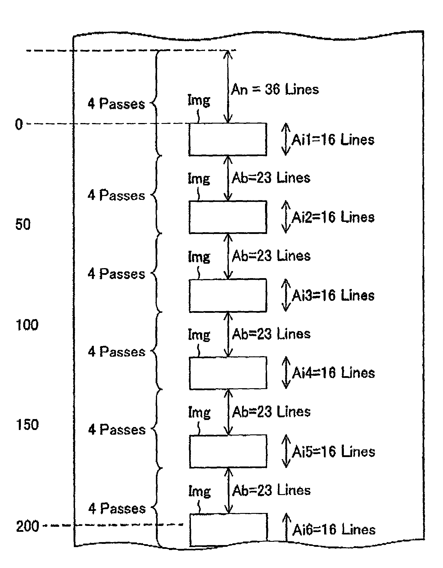
[0083](1) Paper Conserving Mode: FIG. 13 illustrates how the main scan lines are printed by which nozzles in paper conserving mode. The symbols in the figure are the same as inFIG. 4, As is evident in FIG. 13, in paper conserving mode in the second example, three nozzles (nozzles #1 through #3) are used in printing for sub-scanning feed 3 dots at a time. In this type of printing, the printable area Ap is the area equal to 2 lines below nozzle #2 (of the printing nozzle row at the start of printing) and the area below. As a result, when images with a range of 16 lines in the sub-sc...


PUM


Abstract

When a relatively large image in the sub-scanning direction is to be printed, a relatively large number of dot-forming elements among a plurality of dot-forming elements are used to form dots by means of sub-scanning with a relatively large average feed. When a relatively small image in the sub-scanning direction is to be printed multiple times at different positions in the sub-scanning direction on the same print medium, a relatively small number of dot-forming elements among the plurality of dot-forming elements are used to form dots by means of sub-scanning with a relatively low average feed. With this embodiment, large images are rapidly printed, and small images are printed more efficiently on printing paper.

Description

BACKGROUND OF THE INVENTION[0001]1. Field of the Invention[0002]The present invention relates to a technique for printing dots on the surface of a print medium using dot printing heads, and in particular to a technique for efficiently printing large and small images.[0003]2. Description of the Related Art[0004]Printers which eject ink from the nozzles of printing heads have recently come to enjoy broad popularity as computer output devices. Such printers with numerous nozzles can print dots for rapid printing of large images by using these numerous nozzles at once. These techniques are disclosed, for example, in Japanese Unexamined Patent Application (Kokai) 2001-232806.[0005]FIG. 19 illustrates an example of interlace printing. Interlace printing is sometimes employed in the above printers in order to achieve high quality printing. During interlace printing, various parts of the printed image Img are printed with various nozzles For example, the parts at the top edge of the image I...

Claims


Application Information

Patent Timeline
Patent Type & Authority Patents(United States)
IPC IPC(8): B41J29/38B41J11/42
CPCB41J11/425
Inventor YOSHIDA, MASAHIKO
Owner SEIKO EPSON CORP
Why Eureka
Try Eureka