
Coin receiving and disbursing apparatus

a technology for receiving and disbursing coins, applied in coin counters, coin/paper handlers, instruments, etc., can solve the problems of reducing the expected life of the hopper, affecting the operation of the hopper, and the rotating disc not being able to contact the retaining bowl, so as to reduce the possibility of damage and minimize oscillation and vibration.

Active Publication Date: 2008-05-27
ASAHI SEIKO CO LTD
View PDF5 Cites 4 Cited by
  • Summary
  • Abstract
  • Description
  • Claims
  • Application Information

AI Technical Summary

Benefits of technology

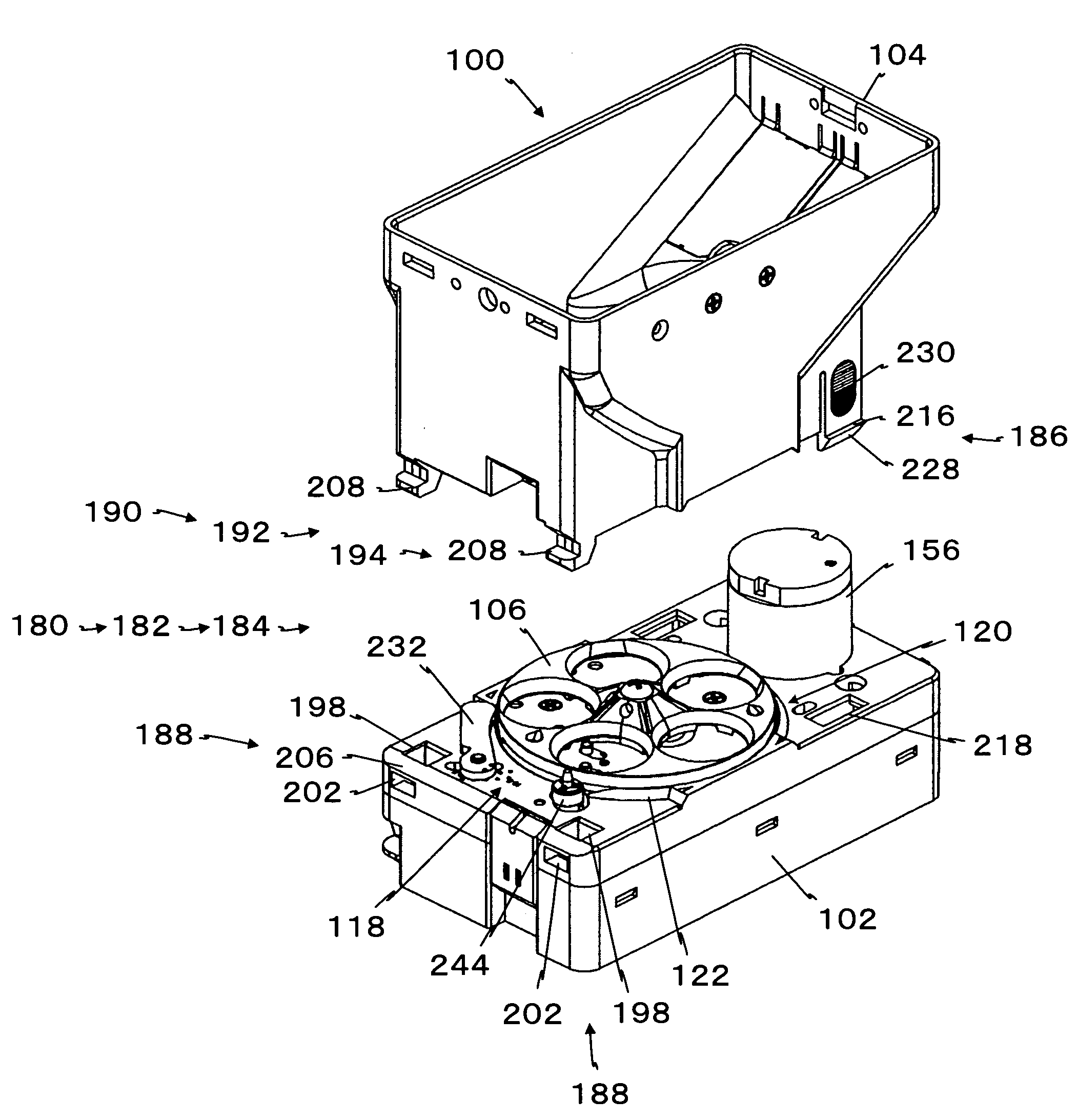
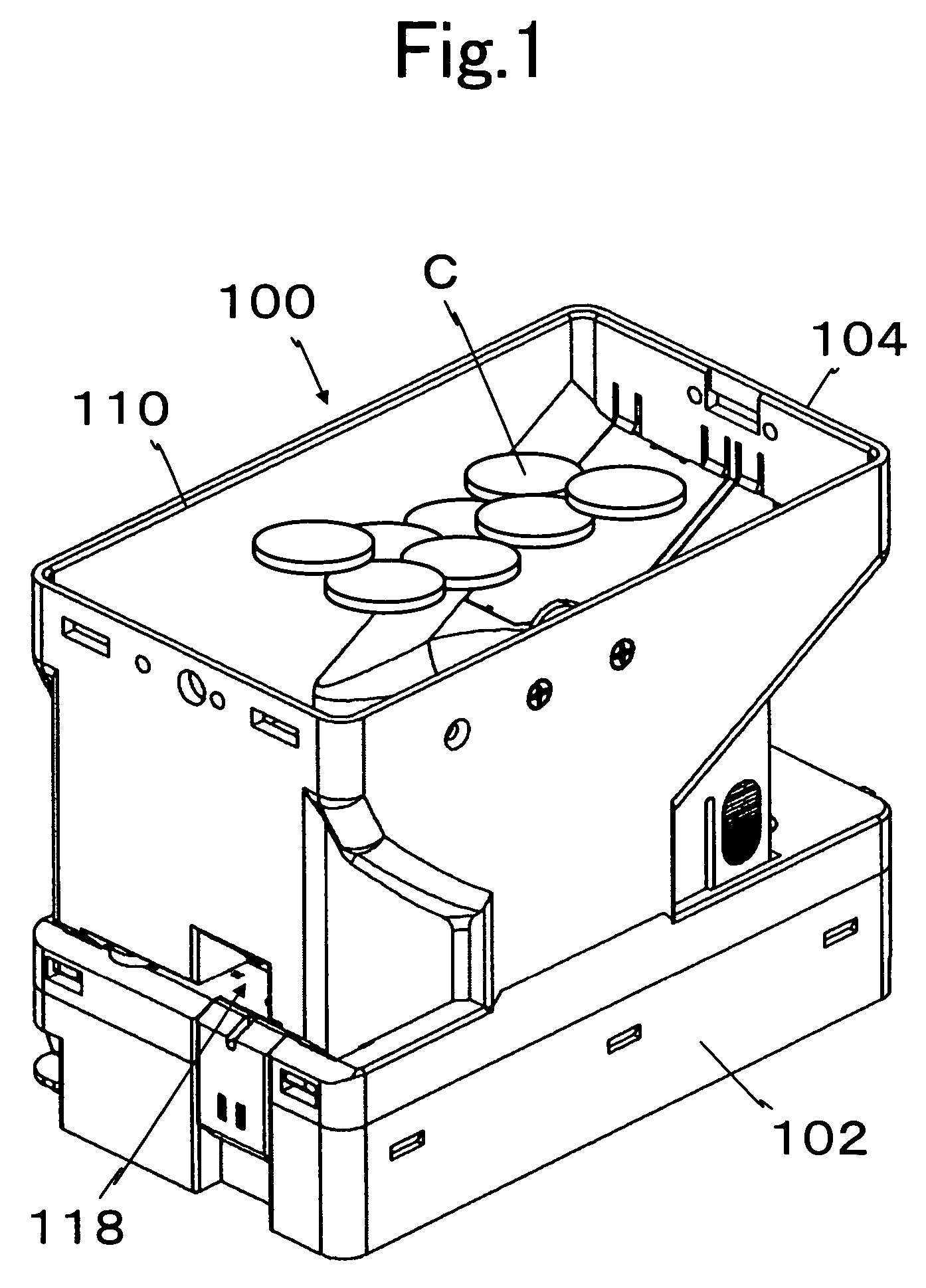
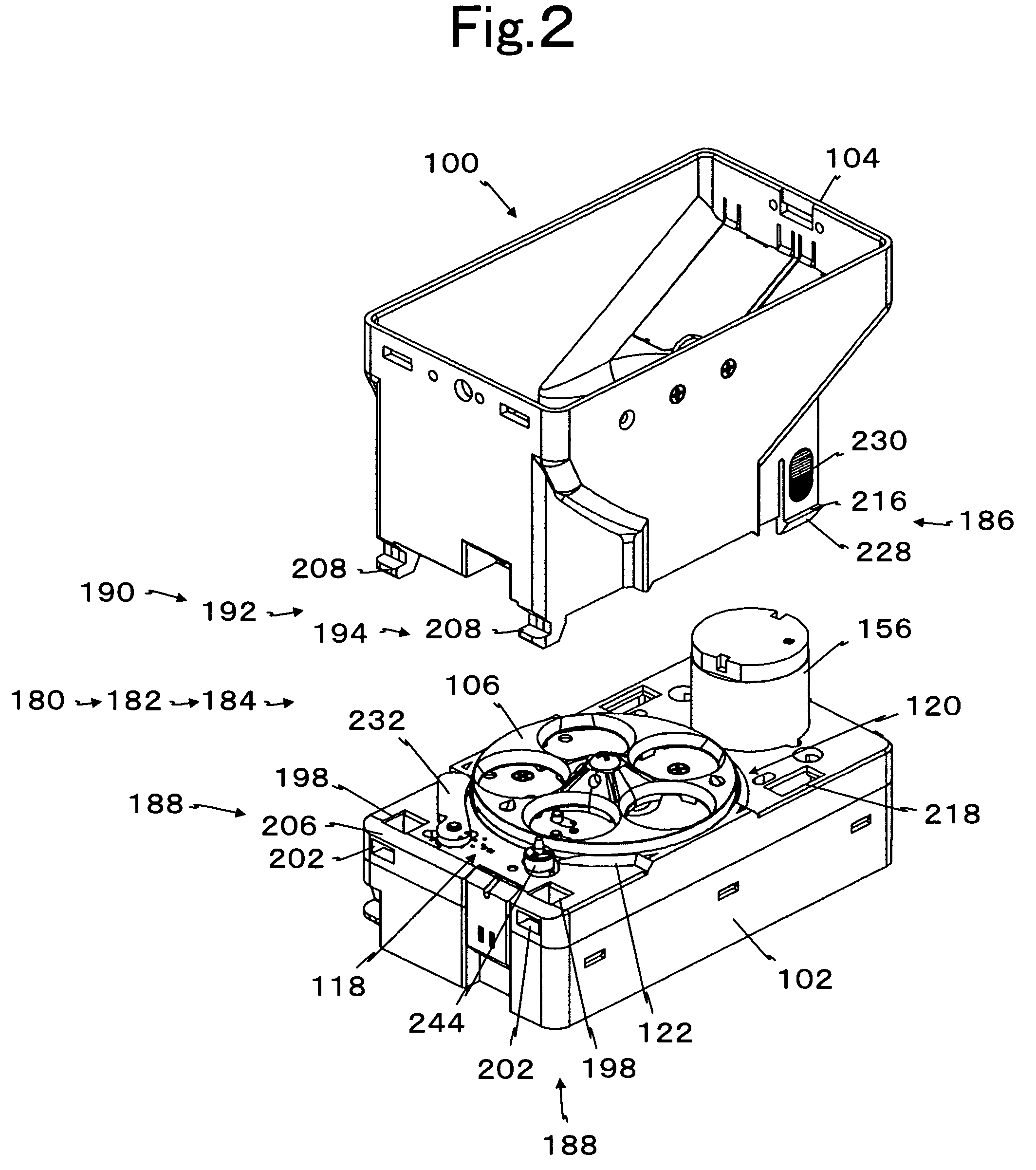
The present invention is a coin receiving and disbursing apparatus that allows for easy attachment and detachment of a retaining bowl to a base without concern for the rotating disc coming into contact with the bowl during operation. The apparatus includes a coin hopper with a rotational disc and a retaining bowl attached to the base. The bowl is attached to the base using complementary slopes in the base and the bowl, which allow the bowl to be automatically aligned with the rotational disc. The bowl is fixed in a fixed position and is supported by the slopes when there is a gap between the base and the bowl. The invention also features the contacting portion between the base and the bowl being located adjacent to the peripheral surface of the rotating disc to prevent coins from coming into contact with the contacting portion. The invention can also have a one-touch attachment device for securely attaching the bowl to the base. The hooks of the attachment units restrict the movement of the bowl in the right and left direction and in the fore-and-aft direction, ensuring secure attachment of the bowl to the base. The bowl can also be easily detached from the base using the elastically latched hook.

Problems solved by technology

When the first and the second latches are poorly aligned, the retaining bowl is not properly positioned, leading to the possibility that the rotating disc will contact the retaining bowl.
In addition, since the second latch is attached by a spring, it is necessary to make the spring force large enough to prevent the retaining bowl from vibrating during operation, further complicating attachment and detachment of the retaining bowl.
If the spring force is reduced to make detachment easier, the retaining bowl may vibrate during operation reducing the expected life the hopper.

Method used


Image

  • Coin receiving and disbursing apparatus
  • Coin receiving and disbursing apparatus
  • Coin receiving and disbursing apparatus

Examples


Embodiment Construction

[0027]Reference will now be made in detail to the preferred embodiments of the invention which set forth the best modes contemplated to carry out the invention, examples of which are illustrated in the accompanying drawings. While the invention will be described in conjunction with the preferred embodiments, it will be understood that they are not intended to limit the invention to these embodiments. On the contrary, the invention is intended to cover alternatives, modifications and equivalents, which may be included within the spirit and scope of the invention as defined by the appended claims. Furthermore, in the following detailed description of the present invention, numerous specific details are set forth in order to provide a thorough understanding of the present invention. However, it will be obvious to one of ordinary skill in the art that the present invention may be practiced without these specific details. In other instances, well known methods, procedures, components, an...


PUM


Abstract

The coin hopper has a rotational disc that is attached to a rotational axis protruding from a base that incorporates a drive unit. A retaining bowl is attached to the base to allow coins to be dispensed one by one by a rotational disc located in a circular cavity defined by a lower part of the retaining bowl. Slopes are formed in the base around the rotational disc so as to be point-symmetric about a rotational axis. A complementary slope corresponding to the base slopes is formed in at least a part of the retaining bowl, and the retaining bowl is attached to the base while these slopes are in contact with each other to enable alignment.

Description

CROSS-REFERENCE TO RELATED APPLICATION[0001]This application is based on application number 2005-022260 filed in Japan on Jan. 28, 2005 from which priority is claimed.BACKGROUND OF THE INVENTION[0002]1. Field of the Invention[0003]The present invention relates to a coin hopper that dispenses coins one by one by means of a rotational disc. More specifically, it relates to a coin hopper that allows easy attachment and detachment of a retaining bowl for retaining coins.[0004]2. Description of Related Art[0005]Coin hoppers are used in automatic teller machines, coin dispensers, game machines and other devices. A typical coin hopper includes a base, a detachable retaining bowl for holding coins and a rotating disc for dispensing coins. A “jamming phenomenon” sometimes occurs when a coin is sandwiched between the base and the rotating disc, thereby locking the disc. When this occurs, the retaining bowl must be detached from the base, the coins are removed from the retaining bowl, and the ...

Claims


Application Information

Patent Timeline
Patent Type & Authority Patents(United States)
IPC IPC(8): G07D1/00
CPCG07D9/008
Inventor IRIE, YASUO
Owner ASAHI SEIKO CO LTD
Learn More