
Multi-position articulating mounting apparatus for an electronic device

a technology for mounting apparatuses and electronic devices, applied in the direction of washstands, light support devices, scaffold accessories, etc., can solve the problems of limiting the vehicles on which the device can be effectively mounted, affecting the viewing angle of portable electronic devices, and difficult to mount portable devices in a location. , to achieve the effect of convenient viewing

Inactive Publication Date: 2008-06-03
GARMIN
View PDF85 Cites 60 Cited by
  • Summary
  • Abstract
  • Description
  • Claims
  • Application Information

AI Technical Summary

Benefits of technology

[0011]It is an object of the present invention to provide a mounting apparatus for an electronic device within a vehicle so that the device can be easily viewed and that allows the angle of the device relative to the user to be adjusted.
[0013]It is another feature of this invention to provide a mounting apparatus that allows a device mounted therein to be either raised or lowered, and manipulated relative to the surface on which the apparatus is mounted.
[0014]It is still another object of the present invention to provide a mounting apparatus for an electronic device that allows the electronic device to be mounted within, and removed from, a mounted position using only one hand.

Problems solved by technology

First, it is more difficult to mount a portable device in a location within the vehicle that allows its screen to be easily viewed.
This mounting position presents the challenge of mounting the device in an orientation and position that can be seen and accessed.
Viewing the screen of a portable electronic device can be hampered if the angle of the viewing screen is fixed relative to the surface on which the device is mounted.
A fixed viewing angle may limit the vehicles on which the device can be effectively mounted due to varying dashboard configurations as well as varying driver and passenger heights.
In other words, a fixed viewing angle may impair the user's ability to effectively and comfortably view the screen.
Second, these electronic devices are often under-utilized if they are only viewable by the driver of the vehicle, but not passengers riding therein.
A rigid mounting apparatus that does not offer the ability to manipulate the orientation of the device relative to the mounting surface is therefore disadvantageous.

Method used


Image

  • Multi-position articulating mounting apparatus for an electronic device
  • Multi-position articulating mounting apparatus for an electronic device
  • Multi-position articulating mounting apparatus for an electronic device

Examples


Embodiment Construction

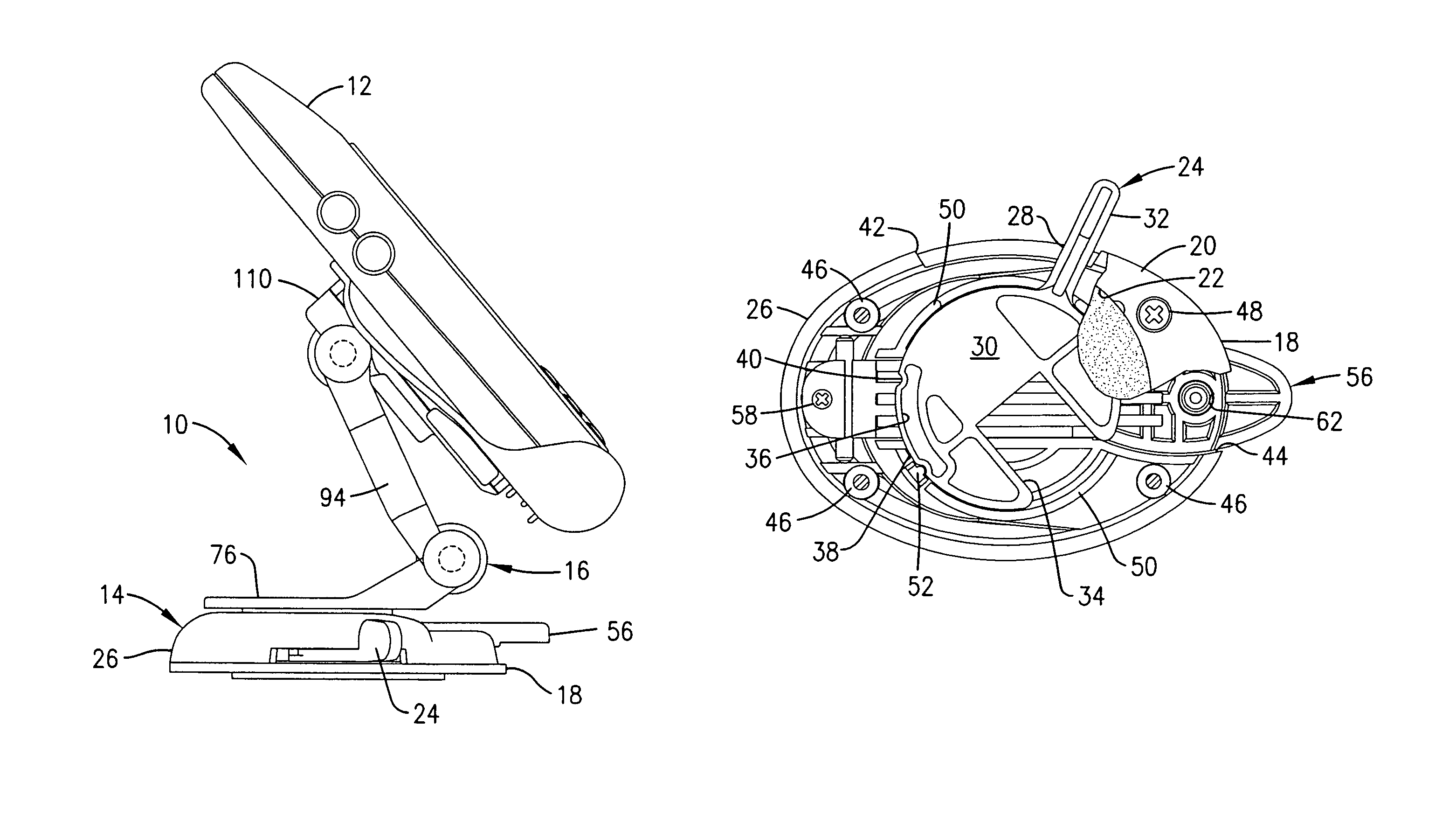
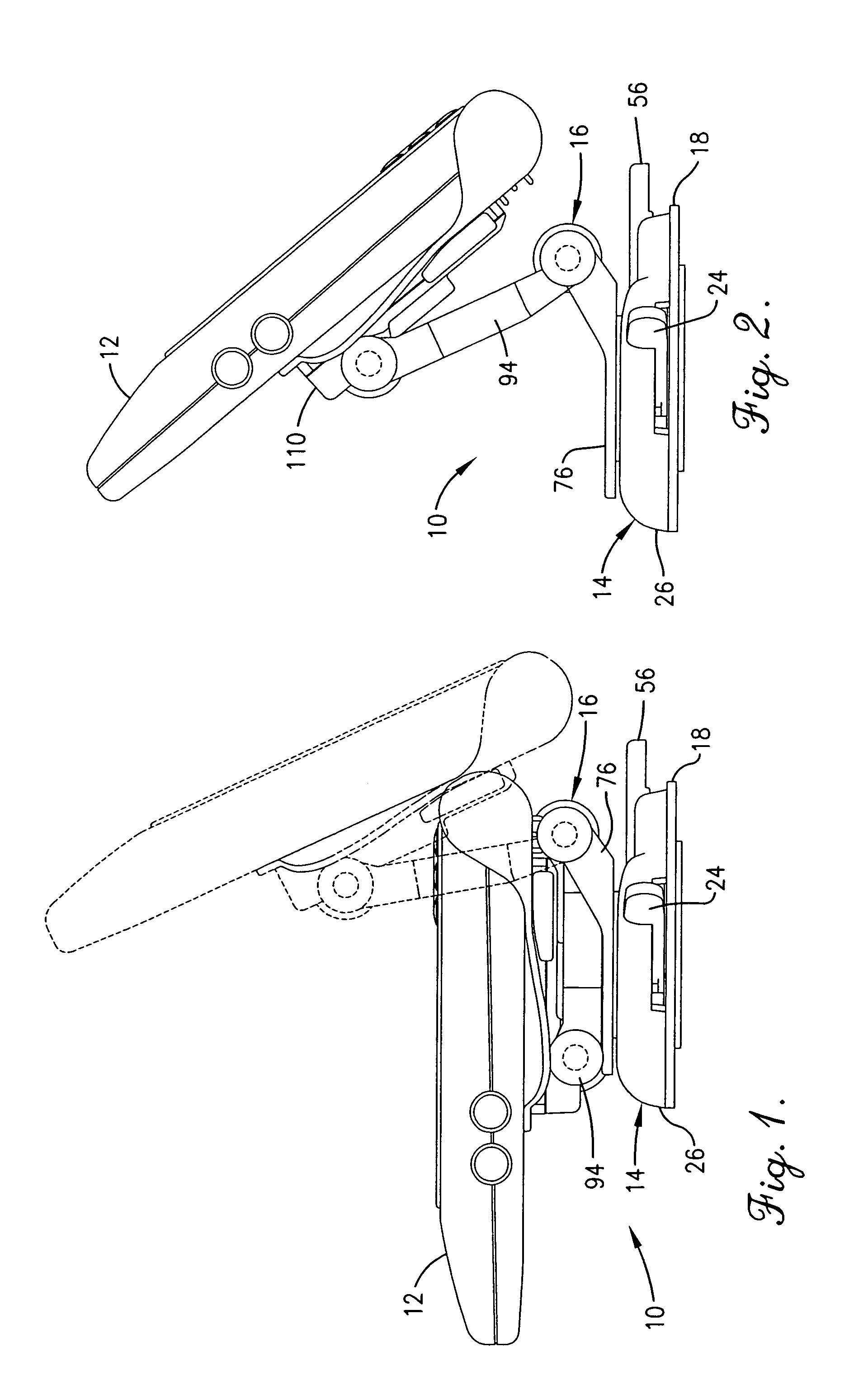
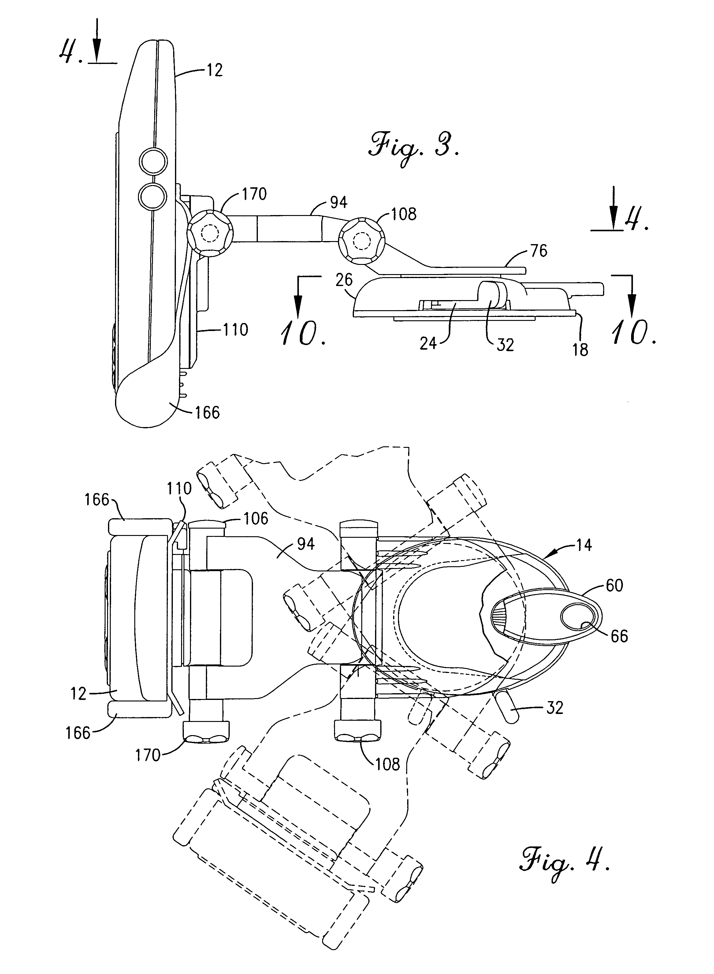
[0039]Referring initially to FIGS. 1 and 2, a mounting apparatus embodying the principles of this invention is broadly designated in the drawings by reference numeral 10. Apparatus 10 is used to hold an electronic device 12 on a surface, such as a vehicle dash. Electronic device 12 can be, for example, a global positioning satellite device. Such a device normally includes some type of viewing screen, which visually conveys information to the user of the device. Apparatus 10 includes a base 14 and a mounting bracket 16. As described below, base 14 is coupled to the desired surface and is used to releasably hold mounting bracket 16. Bracket 16 is releasably coupled to the electronic device and is constructed to be releasably held within base 14.

[0040]Base 14 is constructed and assembled as described in U.S. Pat. No. 6,129,321, entitled Mounting Apparatus For An Electronic Device, the specification of which is hereby incorporated by reference. As best seen in FIGS. 10-12, base 14 has a...


PUM


Abstract

An apparatus is provided for removably mounting an electronic device to a surface and for positioning the device with respect to the surface. The apparatus includes a cradle securable to the electronic device and a pivot link, which has a first end and a second end. The first end being pivotally coupled to the cradle. The apparatus also includes a support having a mounting pedestal coupled thereto. The second end of the pivot link is pivotally coupled to the support. The apparatus has a base which has a lower face that can be coupled to the surface and an upper face. The upper face has a receiving slot for the pedestal, the slot having a shoulder extending thereabove to engage the pedestal. The slot further has an open end to allow the pedestal to be moved within the slot. The base further includes a releasable locking arm having a retaining ridge located in line with the open end of the slot to selectively hold the pedestal within the slot. The pedestal of the apparatus can be placed within the slot and held within the slot by the retaining ridge of the locking arm. Further, the electronic device can be positioned with respect to the surface by pivoting the cradle and the link, and by rotating the pedestal within the slot. In an alternate embodiment, a suction cup mount is utilized.

Description

[0001]This application is a continuation of Ser. No. 09 / 840,949, filed Apr. 24, 2001, now U.S. Pat. No. 6,663,064 which is a continuation of Ser. No. 09 / 452,409, filed Dec. 1, 1999, now U.S. Pat. No. 6,464,185, which is a continuation of Ser. No. 09 / 208,348, filed Dec. 9, 1998, now U.S. Pat. No. 6,173,933 and a continuation-in-part of Ser. No. 09 / 192,919, filed Nov. 16, 1998, now U.S. Pat. No. 6,129,321.BACKGROUND OF THE INVENTION[0002]1. Field of the Invention[0003]The present invention relates to a mounting apparatus for an electronic device. More specifically, the invention relates to a mounting apparatus for an electronic device for use in a vehicle, which allows the electronic device to be selectively rotated and placed in a number of positions, and which allows the electronic device to be placed within, and removed from, a mounted position with one hand.[0004]2. Description of the Related Art[0005]Electronic devices are being used more and more frequently in vehicles. For exam...

Claims


Application Information

Patent Timeline
IPC IPC(8): F16M11/14
CPCB60R11/02F16M11/04F16M11/041F16M11/10F16M11/12F16M11/2064F16M11/38F16M13/00F16M13/022B60R2011/0056B60R2011/0085F16M2200/024
Inventor WHITESIDE, JOHN B.LAVERICK, DAVID J.
Owner GARMIN
Features
  • Generate Ideas
  • Intellectual Property
  • Life Sciences
  • Materials
  • Tech Scout
  • Unparalleled Data Quality
  • Higher Quality Content
  • 60% Fewer Hallucinations
Learn More