Ink jet recording apparatus
a liquid jet and recording apparatus technology, applied in the direction of printing, inking apparatus, etc., can solve the problems of unstable discharge operation, insufficient supply of ink to the discharge ports, and increase the density of images, so as to reduce the effect of the discharge ports and the temperature distribution of the head
- Summary
- Abstract
- Description
- Claims
- Application Information
AI Technical Summary
Benefits of technology
Problems solved by technology
Method used
Image
Examples
first embodiment
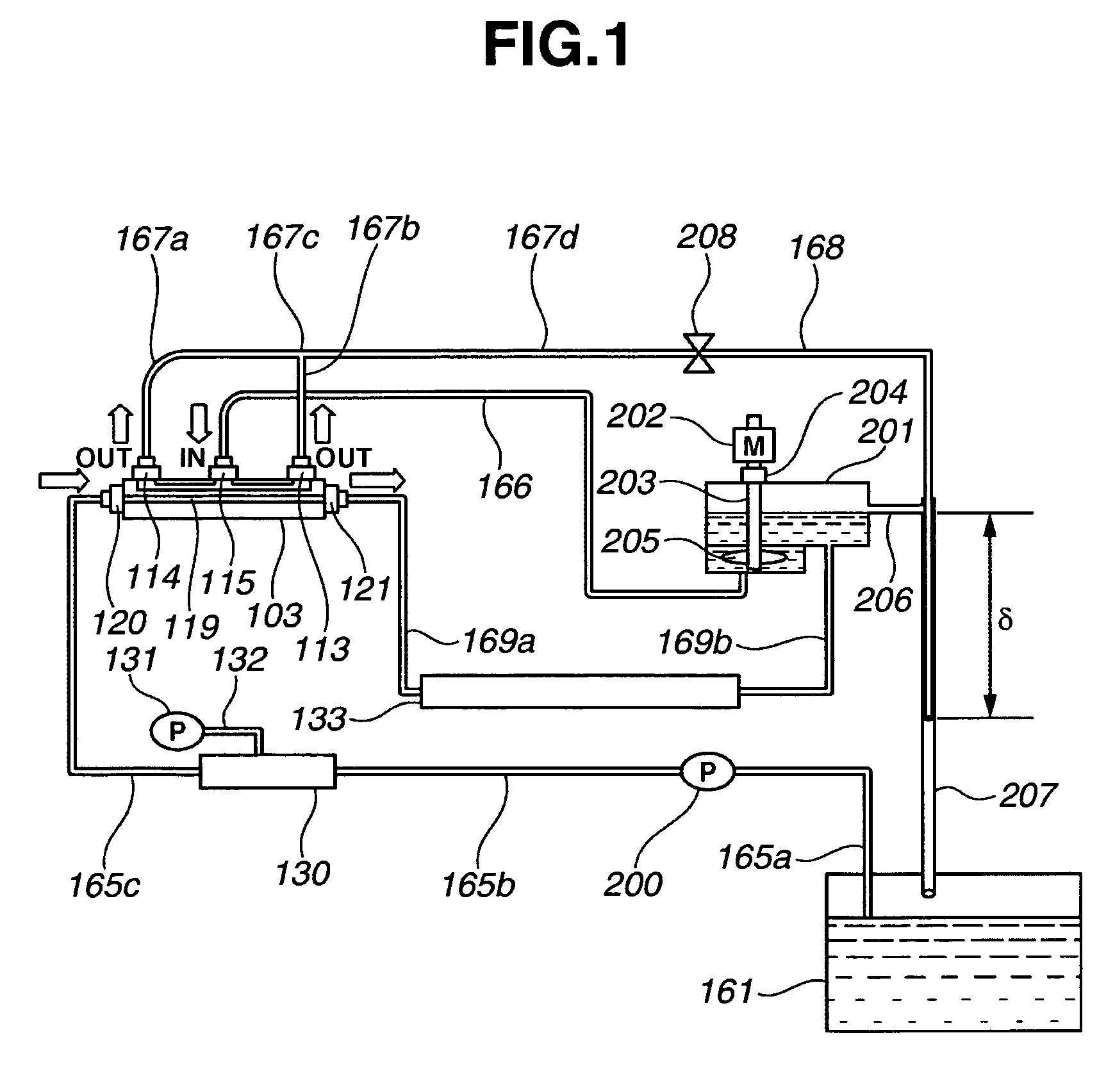
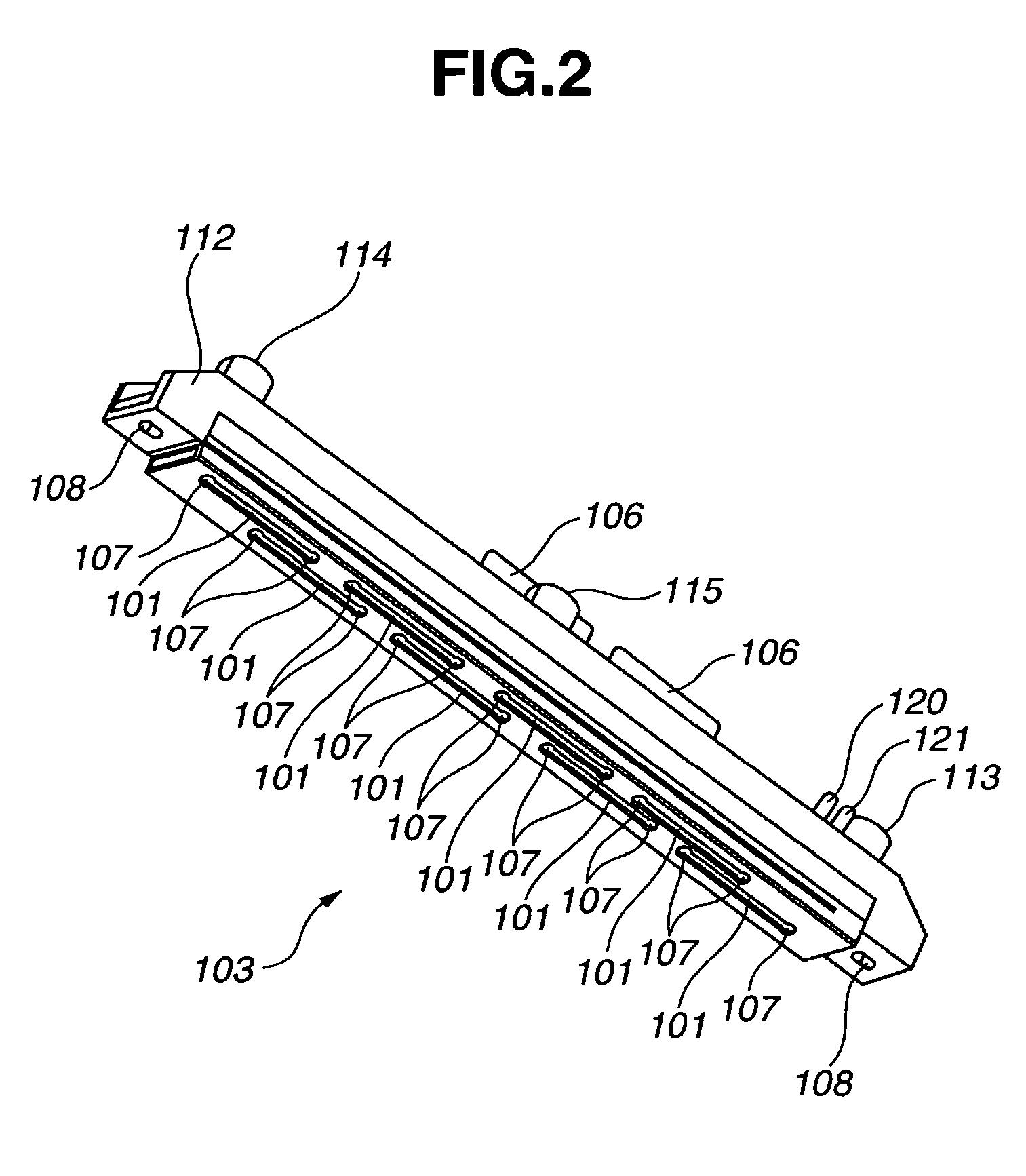
[0078]To begin with, a head configuration of a liquid jet recording apparatus according to a first embodiment of the present invention is described with reference to FIG. 2 through FIG. 7.
[0079]FIG. 2 and FIG. 3 are perspective views showing an ink jet head viewed from the side of a head substrate element and viewed from the side of a liquid supply port, respectively. FIG. 4 and FIG. 5 are views explaining a detailed structure of a base substrate of the head, respectively. FIG. 6A is a front view showing the ink jet head according to the first embodiment of the present invention when viewed from the side of a liquid supply port. FIG. 6B is a cross sectional view taken along line 6B-6B of FIG. 6A. FIG. 6C is a front view showing the ink jet head according to the first embodiment of the present invention when viewed from the side of a liquid discharge port. FIG. 6D is a cross sectional view taken along line 6D-6D of FIG. 6C. FIG. 7 is a side cross sectional view showing the details of...
second embodiment
[0229]A liquid jet recording apparatus according to a second embodiment of the present invention is described below with reference to FIG. 10, FIG. 11A, and FIG. 11B.
[0230]FIG. 10 is a view showing the configuration of an ink supply system of the liquid jet recording apparatus according to the second embodiment of the present invention. FIG. 11A and FIG. 11B are views showing the configuration of a gear pump used as a liquid suction pump 163 in the second embodiment. The configuration of the ink supply system is mostly similar to the configuration as described in the first embodiment. However, some portion of the configuration is different from the configuration as described in the first embodiment. Therefore, an explanation as to the portion that is the same as the configuration in the first embodiment is not repeated here, and the explanation is made only as to the portion that is different from the configuration in the first embodiment.
[0231]In the configuration of the ink supply...
third embodiment
[0288]A liquid jet recording apparatus according to a third embodiment of the present invention is described below with reference to FIG. 12.
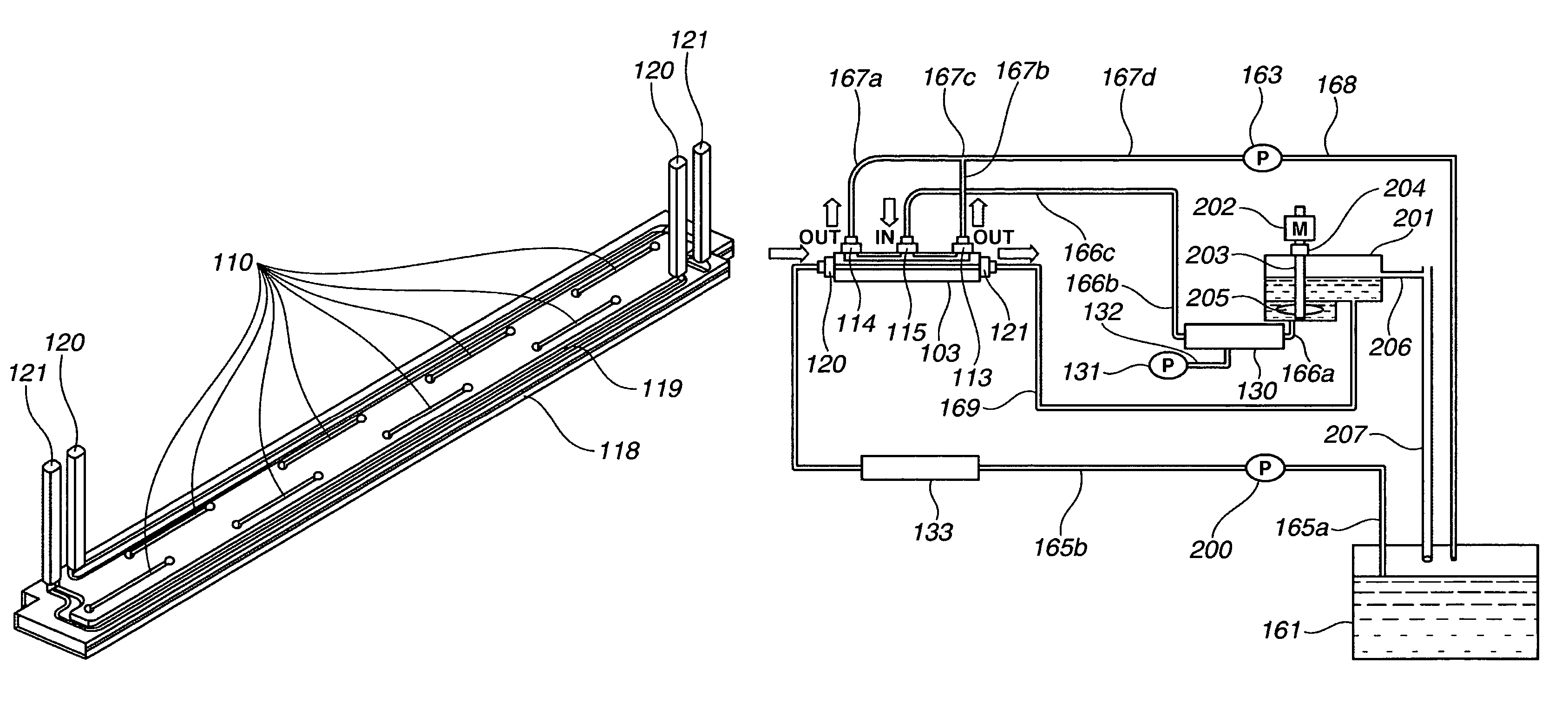
[0289]The third embodiment of the present invention is different from the second embodiment in the points that the de-aerating device 130 is disposed on the downstream side of the sub-tank 201 and that the front end of the tube 168 is connected to the liquid reserve tank 161. Except for these points, the configuration of the third embodiment is similar to the configuration of the second embodiment.
[0290]In the third embodiment, since the de-aerating device 130 is disposed at a position immediately close to the liquid jet head 103, it is possible to allow the capacity of the de-aerating device 130 itself and the capacity of a section including the vacuum pump 131 to be lower than those in the case of the second embodiment.
[0291]Thus, the configuration of the liquid jet recording apparatus according to the third embodiment is more suitable for a ...
PUM
 Abstract
Description
Claims
Application Information
 - R&D
- Intellectual Property
- Life Sciences
- Materials
- Tech Scout
- Unparalleled Data Quality
- Higher Quality Content
- 60% Fewer Hallucinations
Browse by: Latest US Patents, China's latest patents, Technical Efficacy Thesaurus, Application Domain, Technology Topic, Popular Technical Reports.
© 2025 PatSnap. All rights reserved.Legal|Privacy policy|Modern Slavery Act Transparency Statement|Sitemap|About US| Contact US: help@patsnap.com


