Docking device actuated by pressure means

a technology of pressure means and docking devices, which is applied in the direction of metal-working holders, positioning devices, supports, etc., can solve the problems of difficult to test the head using these docking devices, often expensive or complex in their structure, etc., and achieves easy, simple and precise coupling of the handling device, low wear, and high practicability.

Active Publication Date: 2008-06-03
THURMAIER STEFAN
View PDF19 Cites 27 Cited by
  • Summary
  • Abstract
  • Description
  • Claims
  • Application Information

AI Technical Summary

Benefits of technology

[0006]With the aid of the docking device according to the invention, an easy, simple, and precise coupling of the handling device to the test head is possible, since it can be carried out in an automated manner by a pressure means, in particular pneumatic. In comparison with a mechanical actuation of the locking unit, actuation with the support of a pressure means has the further advantage that it can be carried out very rapidly and with low wear. In addition to this, the device can be produced in a simple and economical manner and with few parts.
[0007]According to an advantageous embodiment, the pressure chamber is delimited on one face side by a cover plate of the locking unit, and radially inwards by a sleeve element which surrounds the ball element clamping sleeve co-axially and extends away from the cover plate. In addition, the ball element clamping sleeve has a carrier flange extending radially outwards over the sleeve element, which flange is connected to the ring piston. Such an arrangement can be produced easily and economically, and ensures a perfect function over an extended period of time.
[0008]According to an advantageous embodiment, a spring means is provided on at least the side of the ring piston opposite the pressure chamber, said spring means exerting an axial spring force on the ring piston, which opposes the thrust force of the pressure means. Such spring means, which may consist, for example, of a plurality of springs arranged around the mid-axis of the locking unit, or may also consist of a single spring, makes it possible in a simple manner for a resetting force to be exerted on the ring piston, moving the piston back into its original position, when the pressure chamber is switched to be free of pressure so as to suspend the locking.
[0009]In addition, it is also possible, according to an advantageous embodiment, for a spring means to be provided in the pressure chamber, which spring means exerts an axial spring force on the ring piston. This spring means, which expediently comprises one or more pressure springs, can, on the one hand, support the effect of the pressure means during the displacement of the ring piston, and, on the other hand, in combination with the spring means arranged on the opposite side, can position the ring piston in a zero setting when the pressure means is released from the pressure chamber.

Problems solved by technology

A disadvantage with such known docking devices, however, is the fact that the docking of the test head using these docking devices is not always possible in the simple, easy, and precise manner desired, and, in addition, they are frequently expensive or complex in their structure.

Method used


Image

  • Docking device actuated by pressure means
  • Docking device actuated by pressure means
  • Docking device actuated by pressure means

Examples


Embodiment Construction

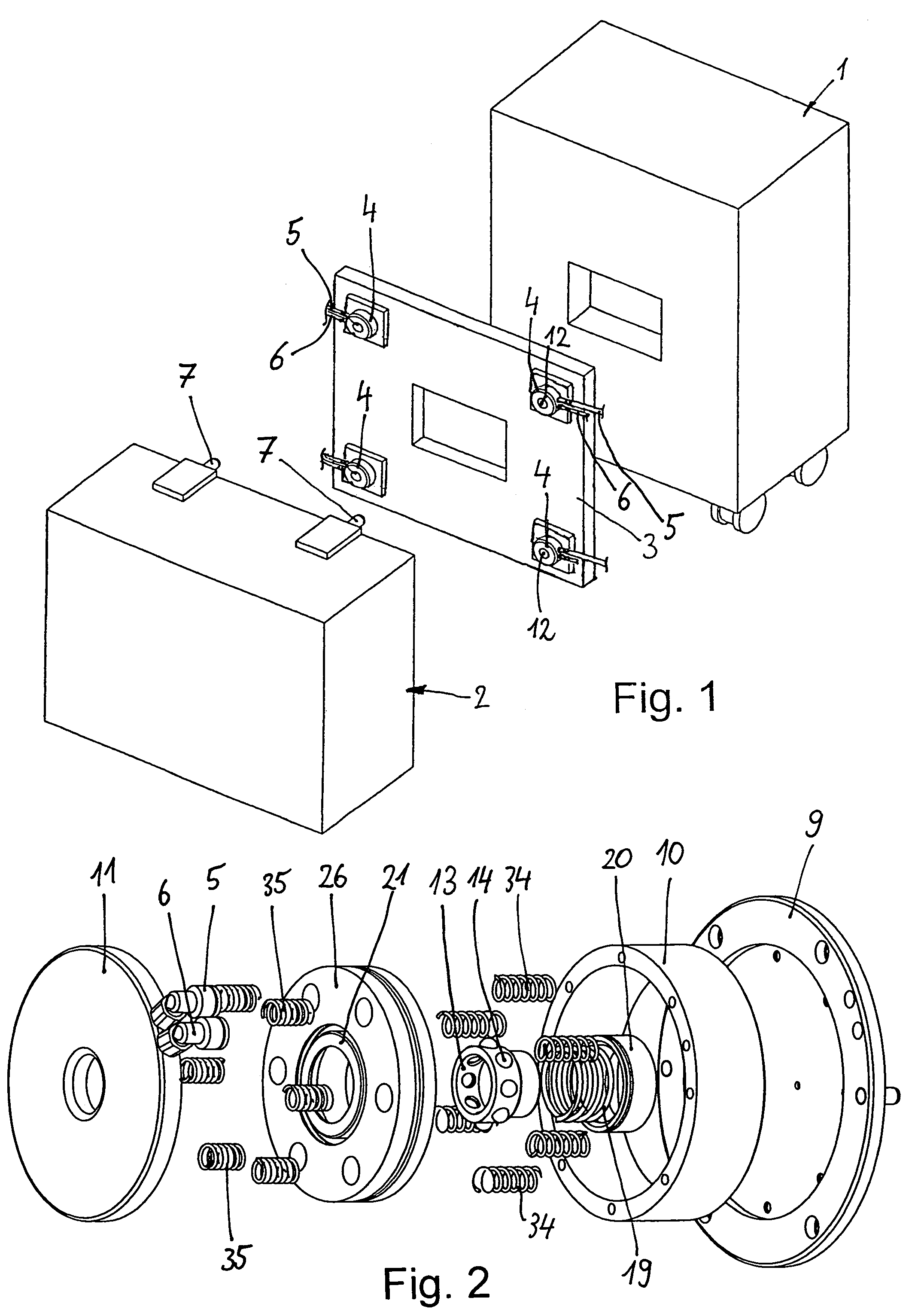
[0017]FIG. 1 shows a diagrammatic representation of a handling device 1, as well as a test head 2. For docking the test head 2 to the handling device 1, a docking plate 3 is used, which can be secured either directly to the handling device 1 or to an intermediate frame, not represented, on which a total of four locking units 4 are secured, arranged in the corner areas of the docking plate 3. The locking units 4 can be actuated by a pressure means, expediently by means of compressed air, which can be introduced to the locking unit 4 via pressure media lines 5, 6, and removed from it via these lines.

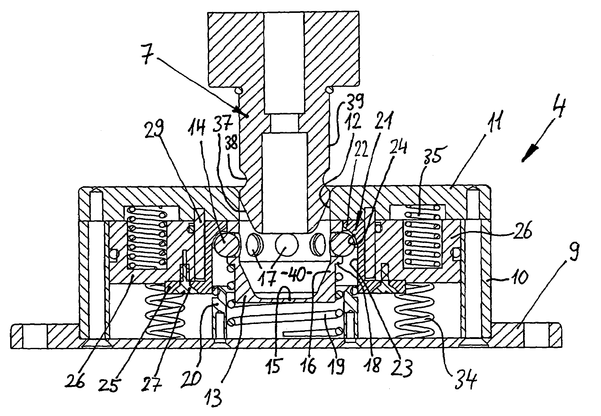
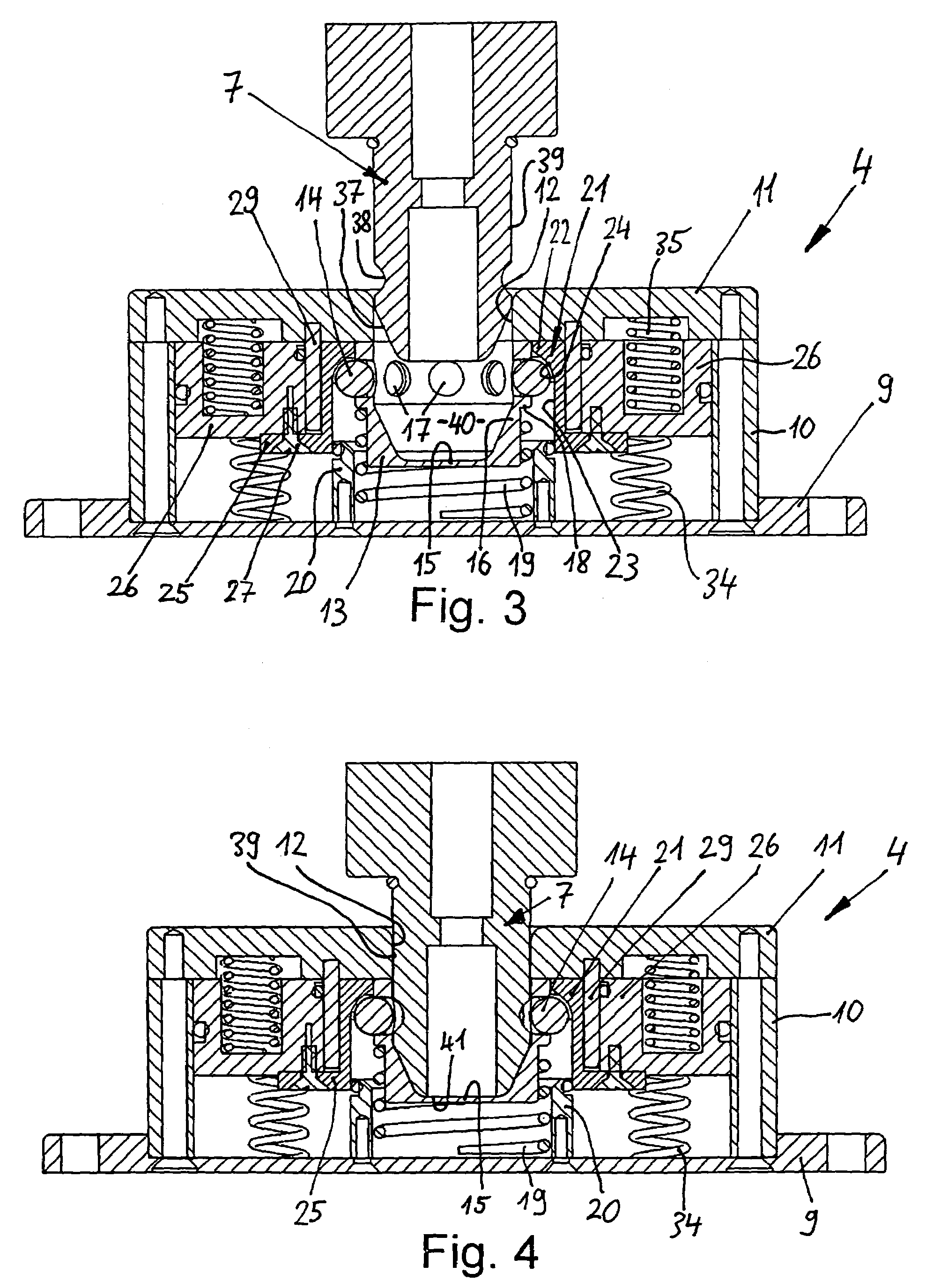
[0018]Secured to the test head 2 are four locking pins 7, which project over the test head 2, and, as will be described in greater detail hereinafter, can be brought into engagement with the locking units 4.

[0019]The docking of the test head 2 to the handling device 1 takes place in such a way that, in the first instance, the test head 2 is moved onto the handling device 1 and onto the doc...


PUM


Abstract

With a docking device for the coupling of a handler or prober to a test head for electronic components, at least one locking unit is provided, which has an axially displaceable ball element clamping sleeve. This ball element clamping sleeve is surrounded by an annular pressure chamber, closing pressure-tight opposite the introduction area of the locking pin and can be moved in an axial direction by means of a ring piston, which can be actuated by a pressure means introduced into the pressure chamber.

Description

BACKGROUND OF THE INVENTION[0001]The invention relates to a docking device for the coupling of a first device including a handler or prober with a second device including a test head for electronic components.[0002]To test electronic components such as, for example, integrated circuits (IC), the principle is known of using a testing device with a test head, which must be connected to a handling device for the electronic components, such as a handler or prober. In order to allow for the docking of the test head, which may weigh up to 1,000 kg, to the handling device in the simplest, easiest, and most precise way possible, special docking devices, i.e. coupling devices, have been developed, which on the one hand are secured to the handling device and, on the other hand, to the test head. A disadvantage with such known docking devices, however, is the fact that the docking of the test head using these docking devices is not always possible in the simple, easy, and precise manner desire...

Claims


Application Information

Patent Timeline
Patent Type & Authority Patents(United States)
IPC IPC(8): G01R31/02
CPCG01R31/2887
Inventor THURMAIER, STEFAN
Owner THURMAIER STEFAN
Why Eureka
Try Eureka