Vehicle LED tail-light bulb

a tail-light bulb and led technology, applied in the direction of fixed installation, lighting and heating equipment, lighting support devices, etc., can solve the problems of not drawing enough current to activate the flasher unit, one light not taking up a lot of space, and the use of less space for led lights

Inactive Publication Date: 2008-06-03
HUANG ZHEN QIU +1
View PDF3 Cites 18 Cited by
  • Summary
  • Abstract
  • Description
  • Claims
  • Application Information

AI Technical Summary

Benefits of technology

[0017]In view of the above disclosure it is the primary object of the invention to produce a vehicle LED tail-light bulb that can directly replace a single or dual-filament incandescent bulb. The LED tail-light bulb allows a conventional vehicle flasher to function and operate the inventive bulb.

Problems solved by technology

Additionally, LED lights require less space and have a longer useful life when compared to incandescent lights.
When the turn signal is turned ON the heater coil heats the contacts causing one of the metal contacts to heat, which in turn causes it to bend.
One light does not draw enough current to heat the metal enough to make it bend.
The same problem arises when you try to substitute a low power LED light in place of a conventional filament light.
They do not draw enough current to activate the flasher unit.

Method used


Image

  • Vehicle LED tail-light bulb
  • Vehicle LED tail-light bulb
  • Vehicle LED tail-light bulb

Examples


Embodiment Construction

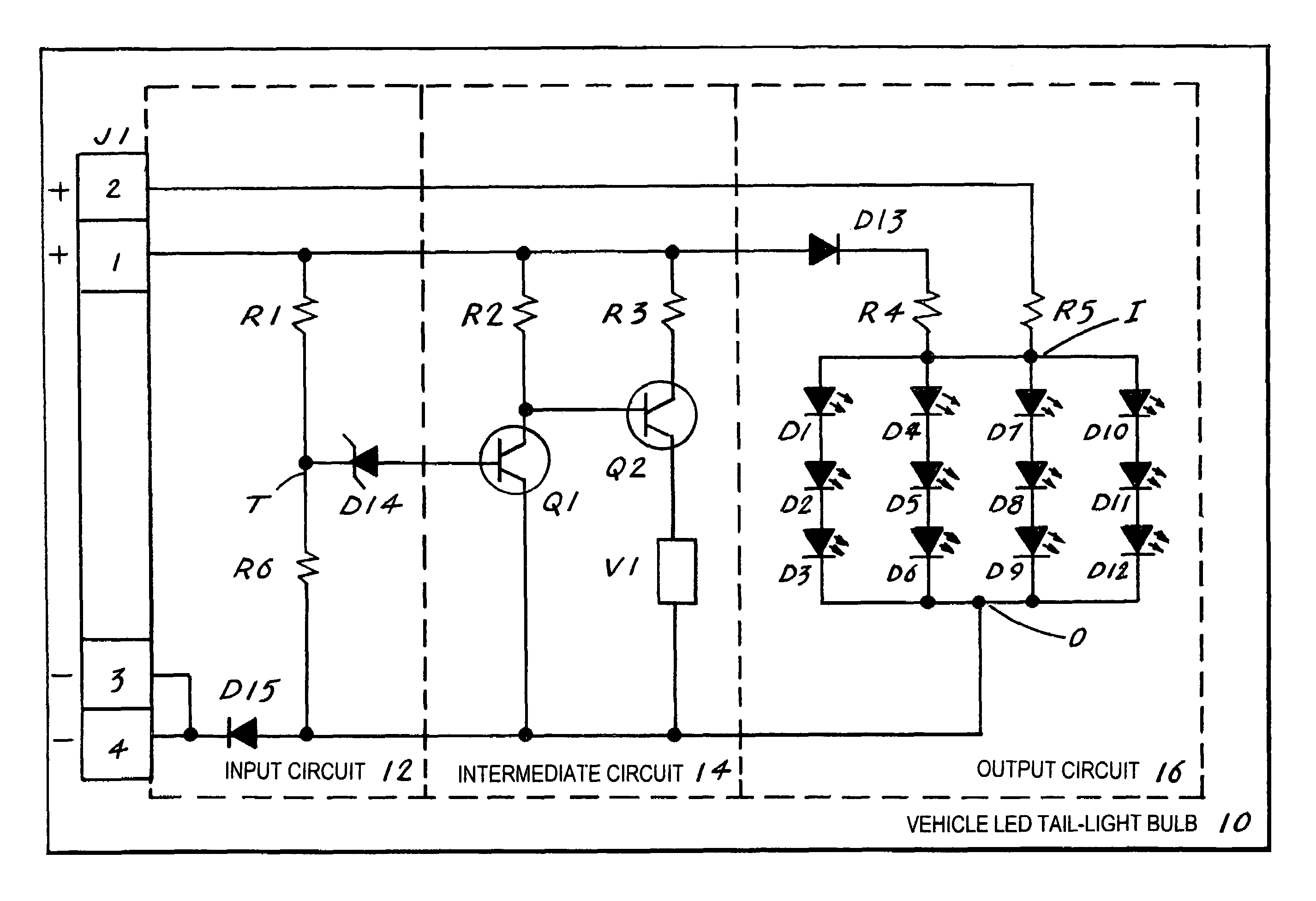
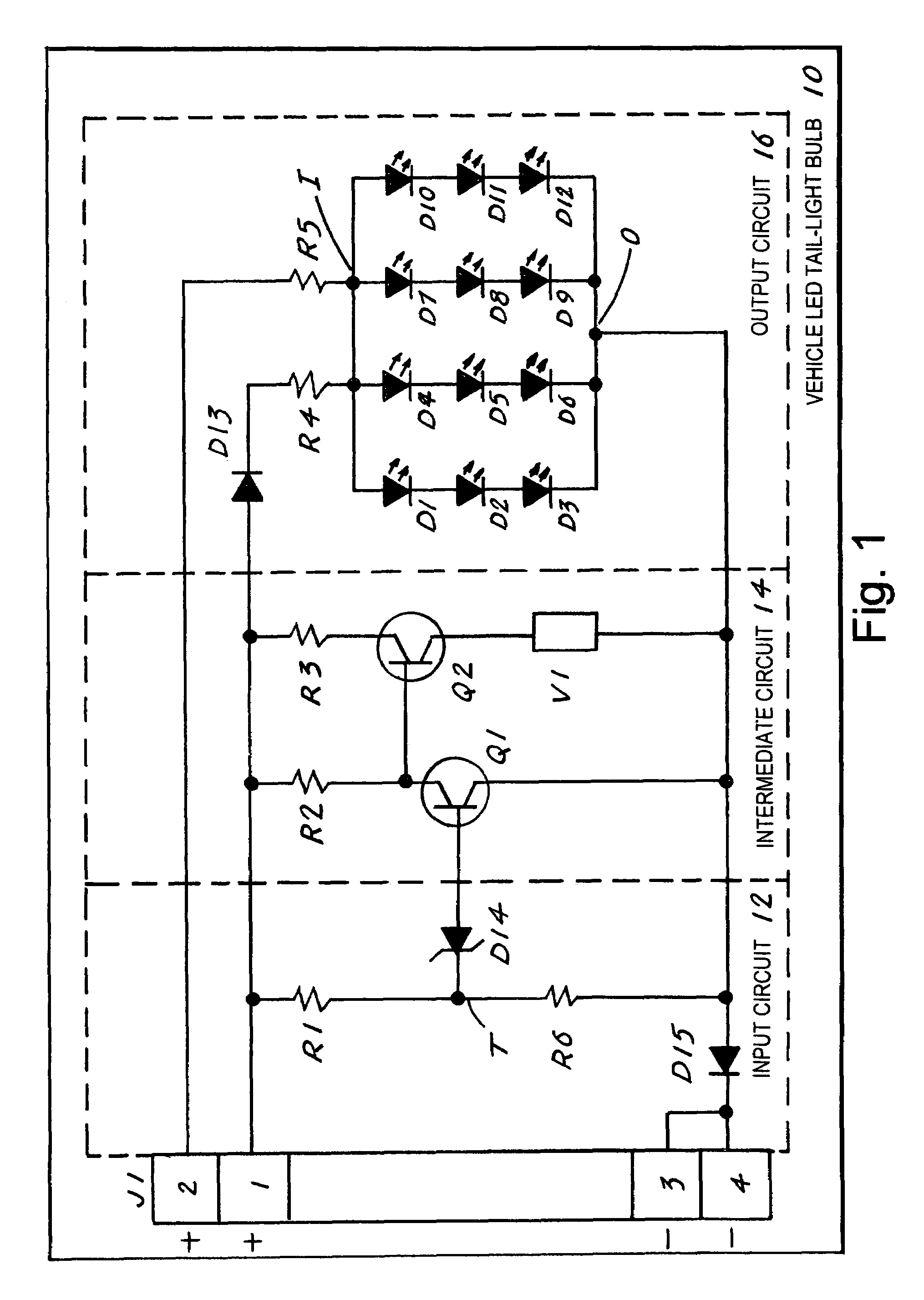
[0027]The best mode for carrying out the invention is presented in terms of a preferred embodiment for a vehicle LED tail-light bulb that is presented in two design configurations. Each design of the LED tail-light bulb 10 (hereinafter “LTLB 10”) is designed to replace a conventional single filament or dual-filament incandescent tail-light bulb that is not shown. The LTLB 10 functions in combination with a corresponding set of right and left vehicle tail-light sockets, a vehicle battery that supplies 12-volts d-c that powers the LTLB 10 and a flasher unit that is energized when a vehicle turn signal arm is placed in either a right or a left turn position. The flasher unit typically includes a set of bimetallic contacts that close when they are heated by a juxtaposed heating element, thus causing the LTLB 10 to blink until the contacts cool, at which time the bulb stops blinking.

[0028]The first design configuration of the LTLB 10, as shown in FIG. 1, is operated by an electronics cir...


PUM


Abstract

A vehicle LED tail-light bulb (10) that is designed to replace an incandescent light bulb, to be inserted into a conventional right and left vehicle light socket and to function in combination with a vehicle battery that powers the bulb (10) and a flasher unit that is activated by a vehicle turn-signal arm. The LED tail-light bulb incorporates an electronics circuit consisting of an input circuit (12), an intermediate circuit (14) and an output circuit (16). The electronics circuit is designed to operate the left and right turn lights and in some cases an emergency light and to produce a current flow of sufficient magnitude to energize the vehicle flasher unit. The energized flasher unit then causes the bulb (10) to blink when the vehicle turn-signal arm is placed in either a right turn or a left turn position.

Description

TECHNICAL FIELD[0001]The invention pertains to the general field of vehicle left and right turn lights, and emergency flashing lights and more particularly to a vehicle LED tail-bulb that produces sufficient current to allow the vehicle left and right turn and emergency lights to illuminate and to blink.BACKGROUND ART[0002]High-intensity LED lights in vehicles are in common use because LED lights are reliable, cost-effective and they produce a greater light output using less power than conventional single or dual-filament incandescent lights. Additionally, LED lights require less space and have a longer useful life when compared to incandescent lights.[0003]The prior art LED light bulbs operate in combination with a flasher unit which causes the lights to turn ON and OFF whenever the right or left turn signal arm or the emergency flasher button is depressed. The flasher unit is constructed using a set of contacts similar to a conventional relay with one exception. One of the relay s...

Claims


Application Information

Patent Timeline
Patent Type & Authority Patents(United States)
IPC IPC(8): B60Q1/34
CPCB60Q1/38B60Q2900/10
Inventor HUANG, ZHEN QIUFU, SAM
Owner HUANG ZHEN QIU
Why Eureka
Try Eureka