Object detector of vehicle

a technology of object detector and vehicle, which is applied in the direction of distance measurement, instruments, and using reradiation, etc., can solve the problems of unsuitable laser strike on the reflector and inability to perform correct distance measuremen

Inactive Publication Date: 2008-06-03
DENSO CORP
View PDF4 Cites 10 Cited by
  • Summary
  • Abstract
  • Description
  • Claims
  • Application Information

AI Technical Summary

Benefits of technology

[0008]It is therefore an object of the present invention to provide an object detector capable of projecting probe light to a reflection object of an obstacle even if the reflection object is positioned at a high position, for instance, in the case where the obstacle is a vehicle having large vehicle height. Thus, object detection or distance measurement can be performed correctly.
[0010]Thus, the rotary body of the object detector includes the first face for projecting the probe light to the first predetermined area and the second face for projecting the probe light to the second predetermined area. By rotating the rotary body, the probe light can be projected to the first predetermined area and the second predetermined area through the projection window. The object detector can project the probe light to a position at a normal height in front of the vehicle. In addition, the object detector can project the probe light to the upper position higher than the normal height in front of the vehicle. As a result, even if a reflection object of an obstacle is positioned at a high position, for instance, in the case of a vehicle having large vehicle height, the probe light can be projected to the reflection object, and the object detection can be performed correctly.

Problems solved by technology

In such a case, there is a possibility that the laser cannot strike the reflector suitably and distance measurement cannot be performed correctly.

Method used


Image

  • Object detector of vehicle
  • Object detector of vehicle
  • Object detector of vehicle

Examples


first embodiment

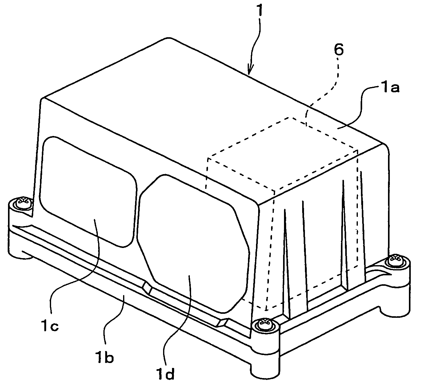
[0022]Referring to FIG. 1, an object detector according to a first embodiment of the present invention is illustrated.

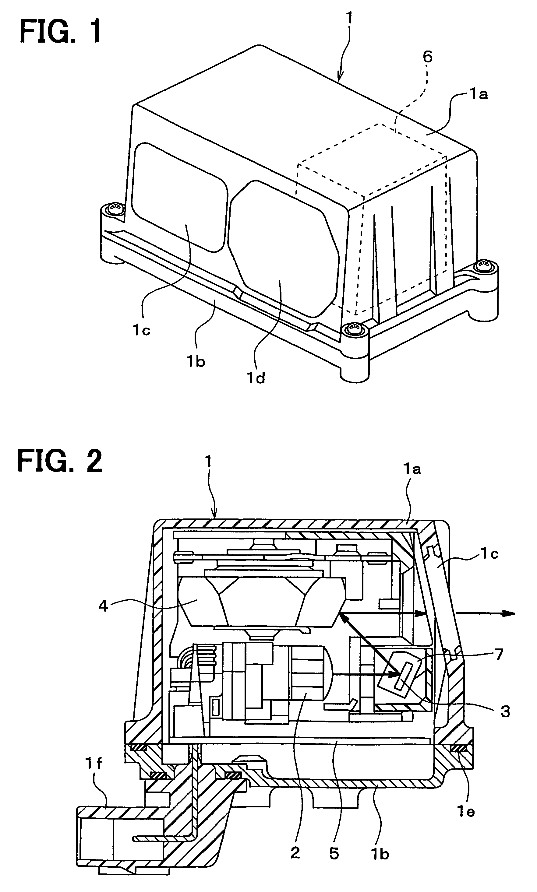
[0023]The object detector shown in FIG. 1 is mounted in a vehicle. The object detector is positioned so that a right side of the object detector in FIG. 2 is directed ahead of the vehicle, for instance. The object detector of the present embodiment is used as a laser radar for detecting an obstacle such as a preceding vehicle (a vehicle in front) or for measuring a distance between the obstacle and the own vehicle during automatic cruise control (adaptive cruise control), for instance.

[0024]Various parts of the object detector are accommodated in a resin case 1 substantially in the shape of a cube as shown in FIGS. 1 to 3.

[0025]The case 1 is formed by a first case portion 1a and a second case portion 1b. The first case portion 1a is formed in the shape of a box formed with an opening in one face thereof. The various parts are accommodated in an accommodation space pr...

second embodiment

[0051]Next, an object detector according to a second embodiment of the present invention will be explained based on FIG. 6.

[0052]As shown in FIG. 6, a polygon mirror 4 of the object detector of the second embodiment is formed in the shape of a truncated six-sided pyramid. Six side faces of the truncated six-sided pyramid is grouped into three first faces 4a′, 4b′, 4c′ and three second faces 4d′, 4e′, 4f′. The first faces 4a′-4c′ are formed in the shape of flat surfaces. The second faces 4d′-4f′ are formed in the shape of convex surfaces.

[0053]If an angle of an arbitral face 4a′ of the polygon mirror 4 with respect to a bottom surface (an upper surface in FIG. 6) of the truncated six-sided pyramid is θ2 degree, an angle of the face 4d′ next to the face 4a′ is set at θ2′ degree, and an angle of the face 4b′ next to the face 4d′ is set at θ2-Δ2 degree. An angle of the face 4e′ next to the face 4b′ is set at θ2′-Δ2′ degree. Thus, the angles of the contiguous six faces 4a′, 4d′, 4b′, 4e′...


PUM


Abstract

A polygon mirror of an object detector of a vehicle includes first faces for projecting a laser to a first predetermined area and a second face for projecting the laser to a second predetermined area higher than the first predetermined area. The polygon mirror is rotated to project the laser to the first and second predetermined areas through a projection window. Thus, the laser can be projected not only to an area at normal height in front of the vehicle but also to an area higher than the normal height in front of the vehicle. Thus, even if a reflection object of an obstacle is positioned at a high position, probe light can be projected to the reflection object. As a result, object detection or distance measurement can be performed correctly.

Description

CROSS REFERENCE TO RELATED APPLICATION[0001]This application is based on and incorporates herein by reference Japanese Patent Application No. 2004-104119 filed on Mar. 31, 2004.BACKGROUND OF THE INVENTION[0002]1. Field of the Invention[0003]The present invention relates to an object detector mounted on a vehicle for detecting an object such as a preceding vehicle with the use of light waves.[0004]2. Description of Related Art[0005]As a kind of object detector mounted on a vehicle, there is a known distance measurement device (a laser radar) for measuring a distance from an obstacle such as a preceding vehicle (a vehicle in front) with the use of a laser and the like, for instance, as disclosed in JP-A-2002-031685 (Patent Document 1). The distance measurement device makes a laser diode intermittently emit the light ahead of the vehicle. The distance measurement device senses light reflected by the obstacle in front of the vehicle with the use of a photo sensor. The distance measureme...

Claims


Application Information

Patent Timeline
Patent Type & Authority Patents(United States)
IPC IPC(8): G01C3/08G01C3/06A61B18/18G01B11/00G01S7/48G01S7/481G01S17/42G01S17/931G02B5/09G02B26/12
CPCG01S7/4813G01S7/4817G02B5/09G02B26/12G01S17/42G01S17/936G01S17/931
Inventor ADACHI, YOSHIKITERUI, TAKEKAZU
Owner DENSO CORP
Why Eureka
Try Eureka